5–22 469 MOTOR MANAGEMENT RELAY – INSTRUCTION MANUAL
CHAPTER 5: SETTINGS
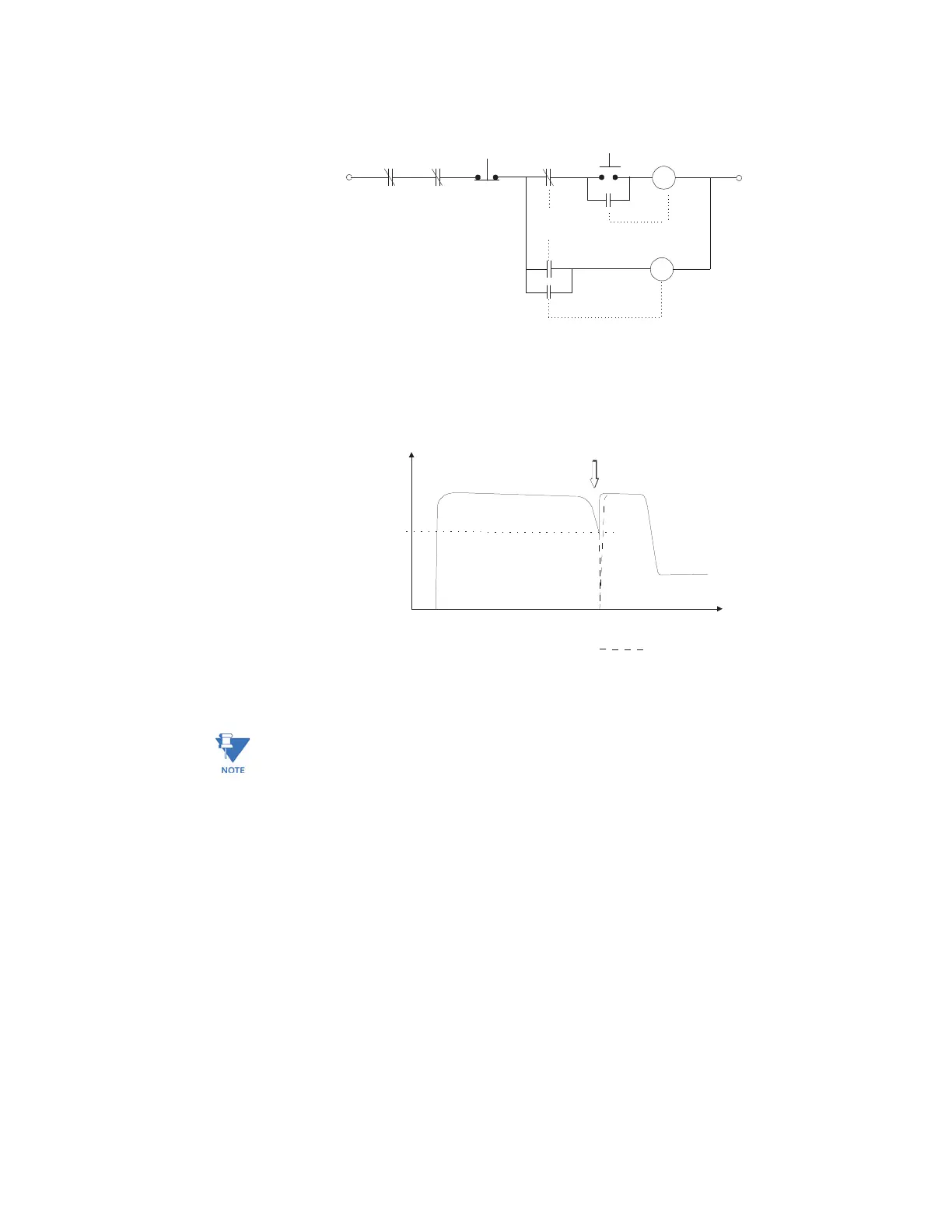
FIGURE 5–1: Reduced Voltage Start Contactor Control Circuit
FIGURE 5–2: Reduced Voltage Starting Current Characteristic
Note
If this feature is used, the Starter Status Switch input must be either from a common
control contact or a parallel combination of Auxiliary ‘a’ contacts or a series combination
of Auxiliary ‘b’ contacts from the reduced voltage contactor and the full voltage contactor.
Once transition is initiated, the 469 assumes the motor is still running for at least 2
seconds. This prevents the 469 from recognizing an additional start if motor current goes
to zero during an open transition.
808724A2.CDR
CC1
CC2
469
BLOCK
TRIP STOP START
REDUCED VOLTAGE
CONTACTOR
FULL VOLTAGE
CONTACTOR
CC1
SEAL IN
469
3AUX
CC2 SEAL IN
808725A1.CDR
MOTOR
AMPS
(% FLA)
When the currrent falls below
the Transition Level and/or the
Timer expires, the Auxiliary
Relay activates for 1 second
Transition Time
TIME
signifies
Open Transition
3 x FLA
Transition
Level
FLA