CHAPTER 6: ACTUAL VALUES
469 MOTOR MANAGEMENT RELAY – INSTRUCTION MANUAL 6–19
• Extremely high unbalance levels (CTs),
• Erroneous power readings (CTs and VTs),
• Phase reversal trips (VTs).
To correct wiring, simply start the motor and record the phasors. The correct phasors can
be determined using the tables along with recorded phasors, system rotation, VT
connection type, and motor power factor. Note that the phase angle for Va (Vab if delta) is
always assumed to be 0° and is the reference for all angle measurements.
Common problems include:
• Phase currents 180° from proper location (CT polarity reversed)
• Phase currents or voltages 120° or 240° out (CT/VT on wrong phase)
An explanation of how the relay identifies and displays system quantities follows. Assume
that the relay is connected to a balanced three-phase system and that V
A
, V
B
, V
C
, and V
COM
are the relay ID names for terminals G2, H1, H2, and G1, respectively.
When the relay is set for the “Open Delta” VT connection type, voltages are measured at
terminals G2 (V
A
) and H2 (V
C
). The voltage at terminal H1 (V
B
) is not measured; however, the
corresponding system quantity is calculated, assuming a balanced three phase system,
where V
A
+ V
B
+ V
C
= 0, leading to V
B
= –(V
A
+V
C
). In the ACTUAL VALUES ZV VOLTAGE
METERING page, the 469 displays only phase-to-phase voltages. The relationship between
the displayed and measured quantities is as follows:
Vab = V
A
Vbc = –V
C
Vca = –(V
A
+V
C
) as calculated
In the
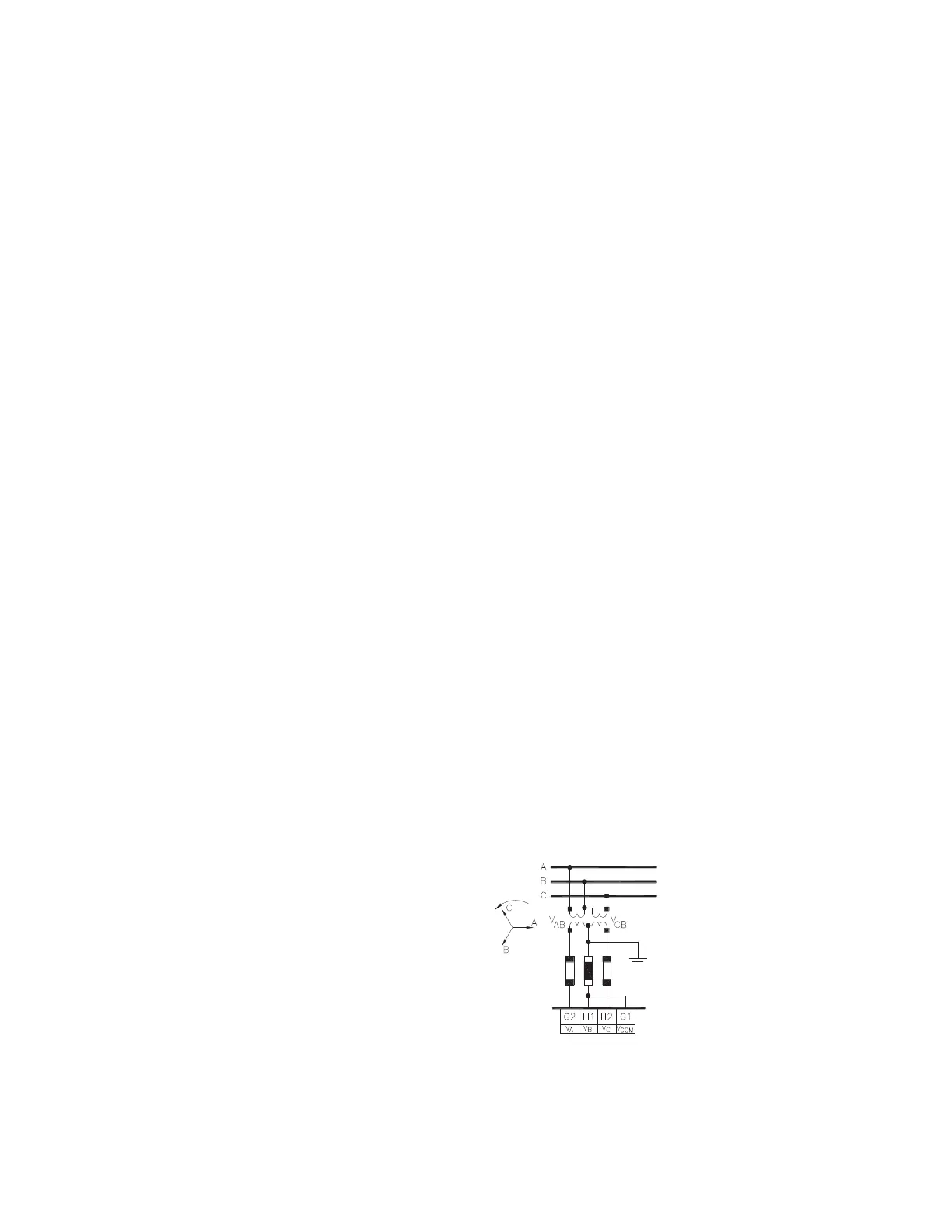
ACTUAL VALUES ZV PHASORS page, the relay displays the relationship between
measured quantities. Refer to the figure below for wiring connections.
• The measured voltage phasor between terminals G2 (V
A
) and G1 (V
COM
) is
displayed by the relay as “Va Phasor” and “Vab” by the EnerVista 469 Setup
software. In this case, Va Phasor is equal to the system quantity Vab.
• The voltage measured between terminals H1 (V
C
) and G1 (V
COM
) is displayed by the
relay as “Vc Phasor” and “Vcb” by the EnerVista 469 Setup software. In this case, Vc
Phasor is equal to the system quantity Vcb or –Vbc.
• The voltage between H2 (V
B
) and G1 (V
COM
) is zero. Hence, the relay displays a
vector with no magnitude.
FIGURE 6–5: Open Delta VT Connection