CHAPTER 6: ACTUAL VALUES
469 MOTOR MANAGEMENT RELAY – INSTRUCTION MANUAL 6–21
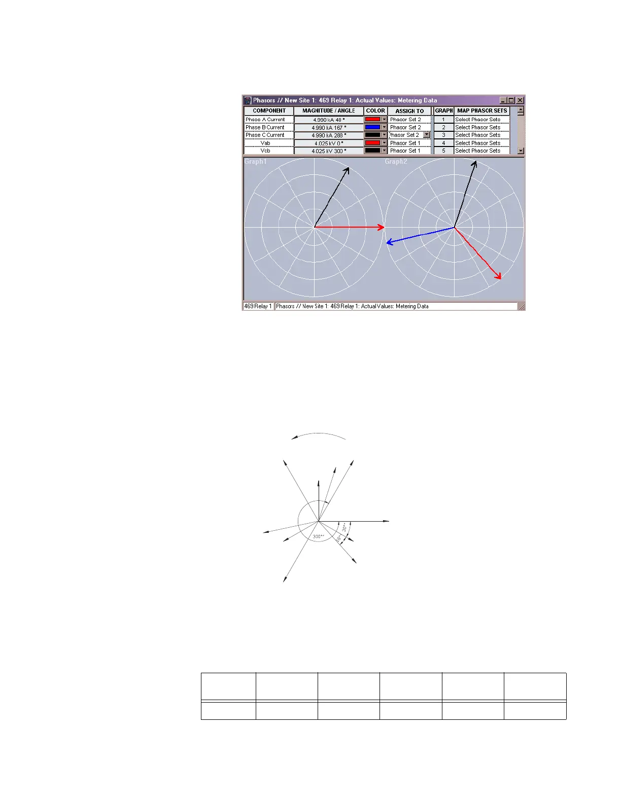
Pressing the “View” button displays the following screen:
The following phasor diagram illustrates the vector diagram of our example. By definition,
power factor is the cosine of the angle between the phase to neutral voltages and the
corresponding phase current. In this example, 18.2° is the angle between Van and Ia, Vbn
and Ib, and Vcn and Ic. Since the relay is measuring phase-phase quantities, and Vab is the
reference phasor, the angle displayed by the relay takes into consideration the 30° angle
between phase-phase and phase-neutral voltages.
FIGURE 6–7: Phasor Diagram for Open Delta Example
Table 6–1: Three-phase Open Delta VT Connection
ABC
Rotation
0.3 pf (72.5°)
lag
0.7 pf
(45°) lag
1.00 pf
(0°) lag
0.7 pf
(45°) lead
0.3 pf (72.5°)
lead
Va 0 0° 0° 0° 0
806559A1.CDR
Phase Rotation
Van
–Vbc
Vca
Ib
Vbn
Ia
Ic
Vcn
Vbc
Vab
System Voltages:
Vab
Vbc
Vca
Measured Voltages:
Vab = VA (G2–G1)
–Vbc = VC (H2 – G1)
Calculated Voltage:
Vac = Vab + Vbc
Displayed Voltages:
Va = Vab
Vb =0°
Vc =–Vbc