CHAPTER 6: ACTUAL VALUES
469 MOTOR MANAGEMENT RELAY – INSTRUCTION MANUAL 6–23
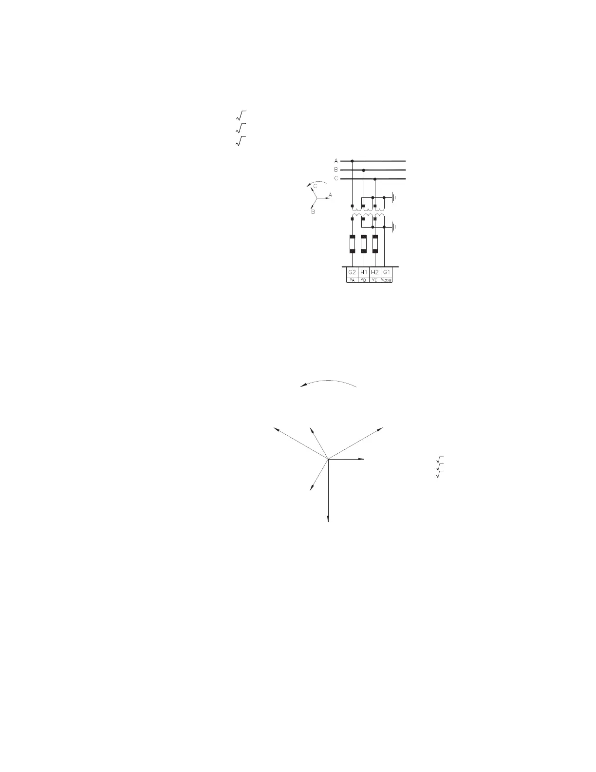
When the relay set for the “Wye” VT connection type, voltages are measured at terminals
G2 (V
A
), H1 (V
B
), and H2 (V
C
) with respect to G1 (V
COM
). Refer to the figure below for details.
The phase-to-phase voltages are calculated using the following relationships:
Vab = × VA
Vbc = × VB
Vca = × VC
FIGURE 6–8: Wye VT Connection
The quantities displayed by the relay and the EnerVista 469 Setup software are
straightforward and follow the phasor diagram shown below. Note that all the angles
shown are negative or lagging angles.
FIGURE 6–9: Typical Phasor Diagram for Wye Connection
Using the same example as for the open delta connection, except for the VT CONNECTION
TYPE
setting to “Wye”, the following quantities are displayed by the relay and EnerVista 469
Setup software:
In the
A2 METERING DATA ZV VOLTAGE METERING menu:
VAB: “4025 Volts”
VBC: “4025 Volts”
VCA: “4025 Volts”
AVERAGE LINE VOLTAGE: “4025 Volts”
VAN: “2323 Volts”
806557A1.CDR
Phase Rotation
System Voltages:
Van; Vab
Vbn; Vbc
Vcn; Vca
Vbn
Vcn
Vab
Vbc
Vca
VC (H2 – G1)
VB (H1 – G1)
VA (G2–G1)
Measured Voltages
Calculated Voltages
Displayed Voltages:
Van = VA
Vbn = VB
Vcn = VC
Vab =As Calculated
Vbc =As Calculated
Vca =As Calculated
Van
VA3Vab ×=
VB3Vbc ×=
VC3Vca ×=