6–24 469 MOTOR MANAGEMENT RELAY – INSTRUCTION MANUAL
CHAPTER 6: ACTUAL VALUES
VBN: “2323 Volts”
VCN: “2323 Volts”
AVERAGE PHASE VOLTAGE: “2323 Volts”
SYSTEM FREQUENCY: “60.00 Hz”
In the
A2 METERING DATA ZV PHASORS menu:
VA PHASOR : “95.8% at 0° Lag”
VB PHASOR: “95.8% at 120° Lag”
VC PHASOR: “95.8% at 240° Lag”
IA PHASOR: “100.0% at 18° Lag”
IB PHASOR: “100.0% at 138° Lag”
IC PHASOR: “100.0% at 258° Lag”
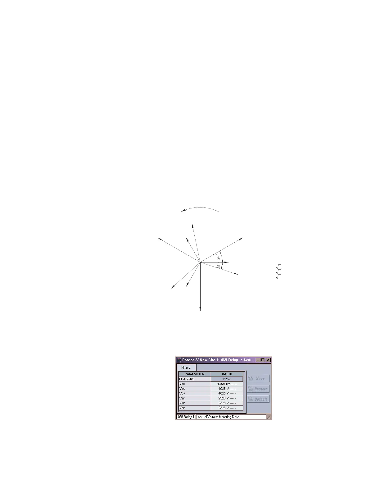
The following phasor diagram illustrates the system vector diagram where the
VT
CONNECTION TYPE
setting is selected as “Wye”. By definition, power factor is the cosine of
the angle between the phase to neutral voltages and the corresponding phase current. In
this example, 18.2° is the angle between Van and Ia, Vbn and Ib, and Vcn and Ic. The
phase-to-phase quantities are not shown in the
A2 METERING DATA ZV PHASORS menu
and the EnerVista 469 Setup software. However, they are shown on the following figure.
FIGURE 6–10: Typical Phasor Diagram for Wye Connection
The EnerVista 469 Setup software displays the following screen:
806563A1.CDR
Ia
Van
Phase Rotation
Vab
Vcn
Vbn
Ic
Vca
Ib
Vbc
System Voltages:
Van; Vab
Vbn; Vbc
Vcn; Vca
VC (H2 – G1)
VB (H1 – G1)
VA (G2–G1)
Measured Voltages
Calculated Voltages
Displayed Voltages:
Van = VA
Vbn = VB
Vcn = VC
Vab =As Calculated
Vbc =As Calculated
Vca =As Calculated
VA3Vab ×=
VB3Vbc ×=
VC3Vca ×=