A–2 469 MOTOR MANAGEMENT RELAY – INSTRUCTION MANUAL
A: APPENDIX
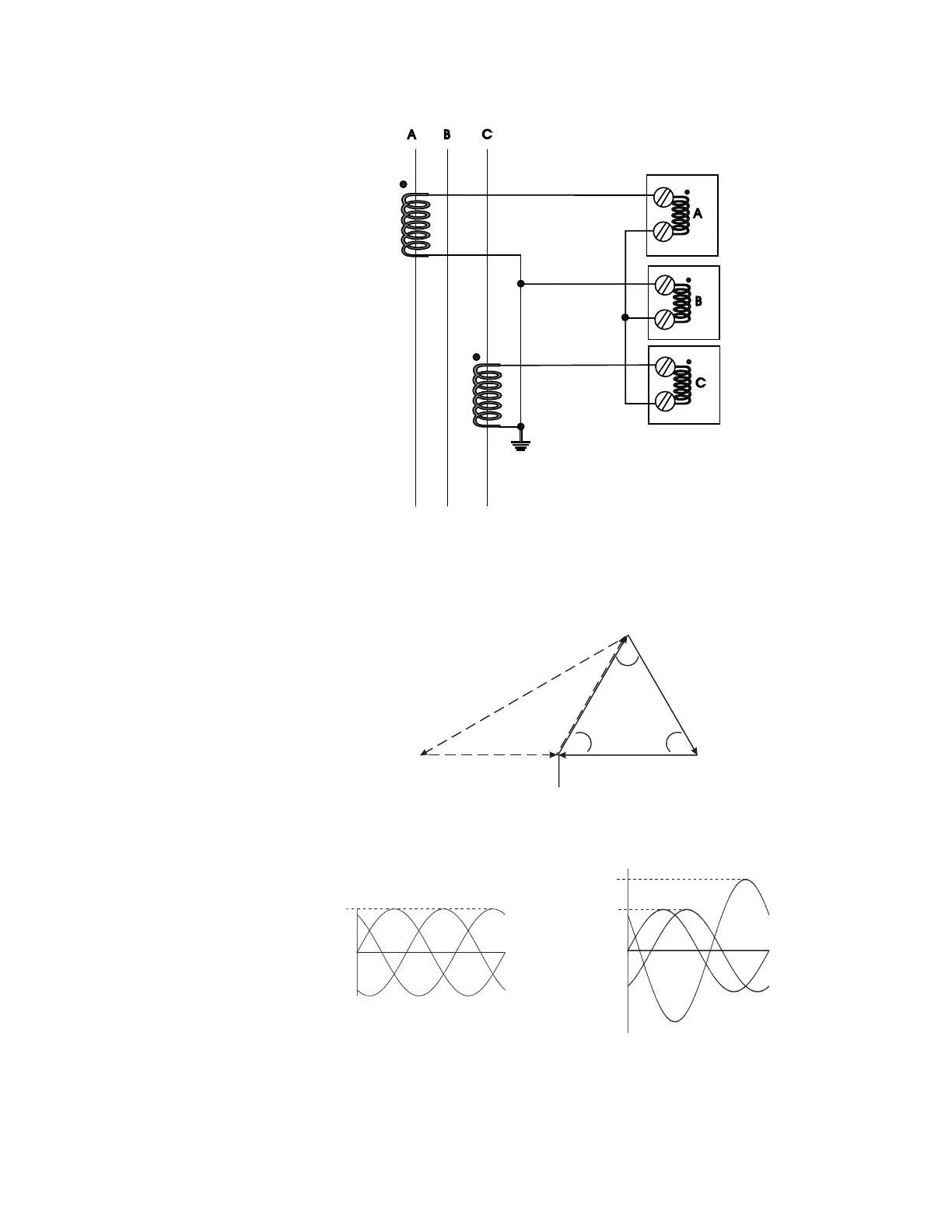
In the two CT configuration, the currents will sum vectorially at the common point of the
two CTs. The diagram illustrates the two possible configurations. If one phase is reading
high by a factor of 1.73 on a system that is known to be balanced, simply reverse the
polarity of the leads at one of the two phase CTs (taking care that the CTs are still tied to
ground at some point). Polarity is important.
To illustrate the point further, the following diagram shows how the current in phases A
and C sum up to create phase 'B'.
808700A1.CDR
A
B
C
A B
C
:5
:5
:5
:COM
:COM
:COM
808702A1.CDR
1.73
11
11
60°
60° 60°
808701A1.CDR
1
C
A
B
1.73
1
B
A
C
2-PHASECT CURRENTS
2-PHASECT CURRENTS
180° OUT-OF-PHASE