Chapter 1. Calibration
2 DigitalFlow™ GF868 Service Manual (1 and 2-Channel)
1.3 Calibrating the Analog Outputs
Every Model GF868 flowmeter includes two built-in analog outputs (A and B) at terminal block I/O, which is
designated as Slot 0. Additional analog outputs may be added to the Model GF868 by installing an Analog Outputs
Option Card in one (or more) of the six expansion slots. Each option card contains four analog outputs, which are
designated as A, B, C and D. Both the zero-point and full-scale values for each output must be calibrated. After
calibrating the outputs, which have a resolution of 5.0 A (0.03% full scale), their linearity should be tested.
Note: The zero point of the analog output may be set for either 0 mA or 4 mA. However, the calibration procedure
always uses the 4 mA point, as the meter will extrapolate this value to obtain the 0 mA point.
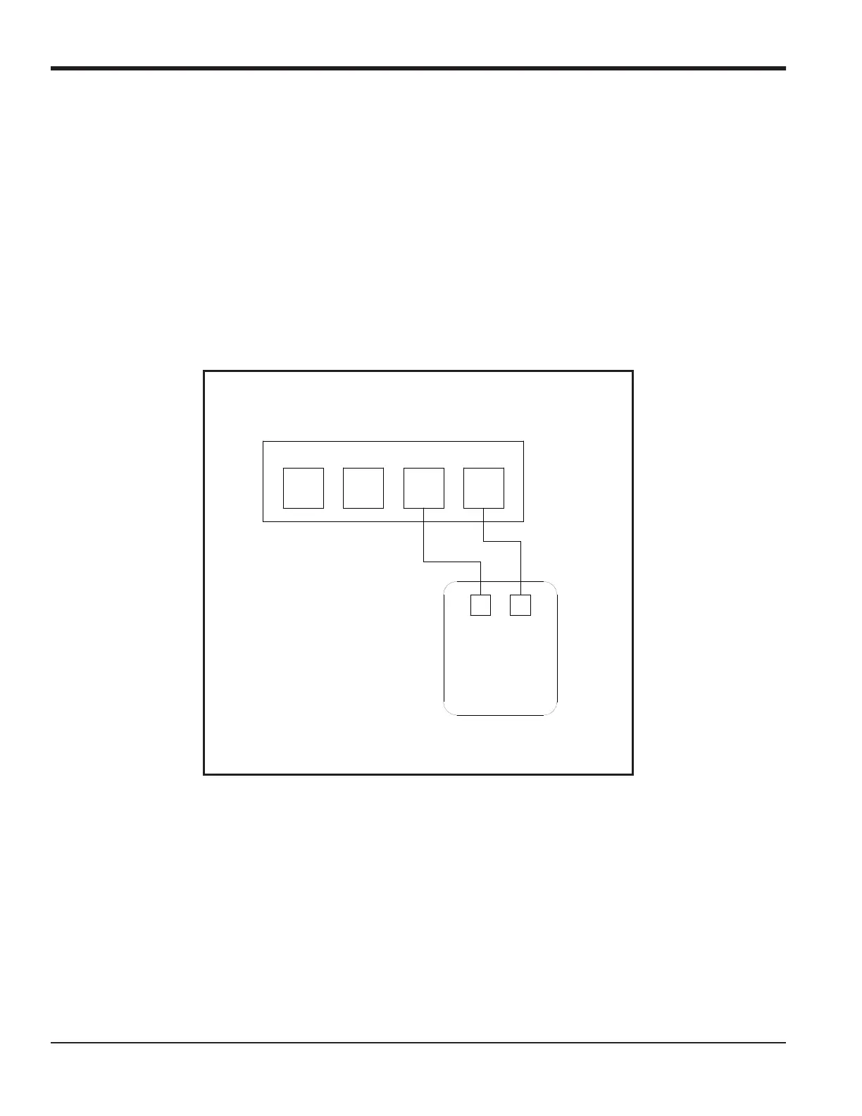
Prepare for the calibration procedure by connecting an ammeter to the desired analog output of Slot X, as shown in
Figure 1 and Figure 2 on page 3 on the next page. Refer to the menu map in Figure 6 on page 15.
Figure 1: Ammeter Connection for Slot 0 (Output A)
Terminal Block I/O (Slot 0)
B
RTN
B
SIG
A
RTN
A
SIG
41
+
-
Ammeter

 Loading...


