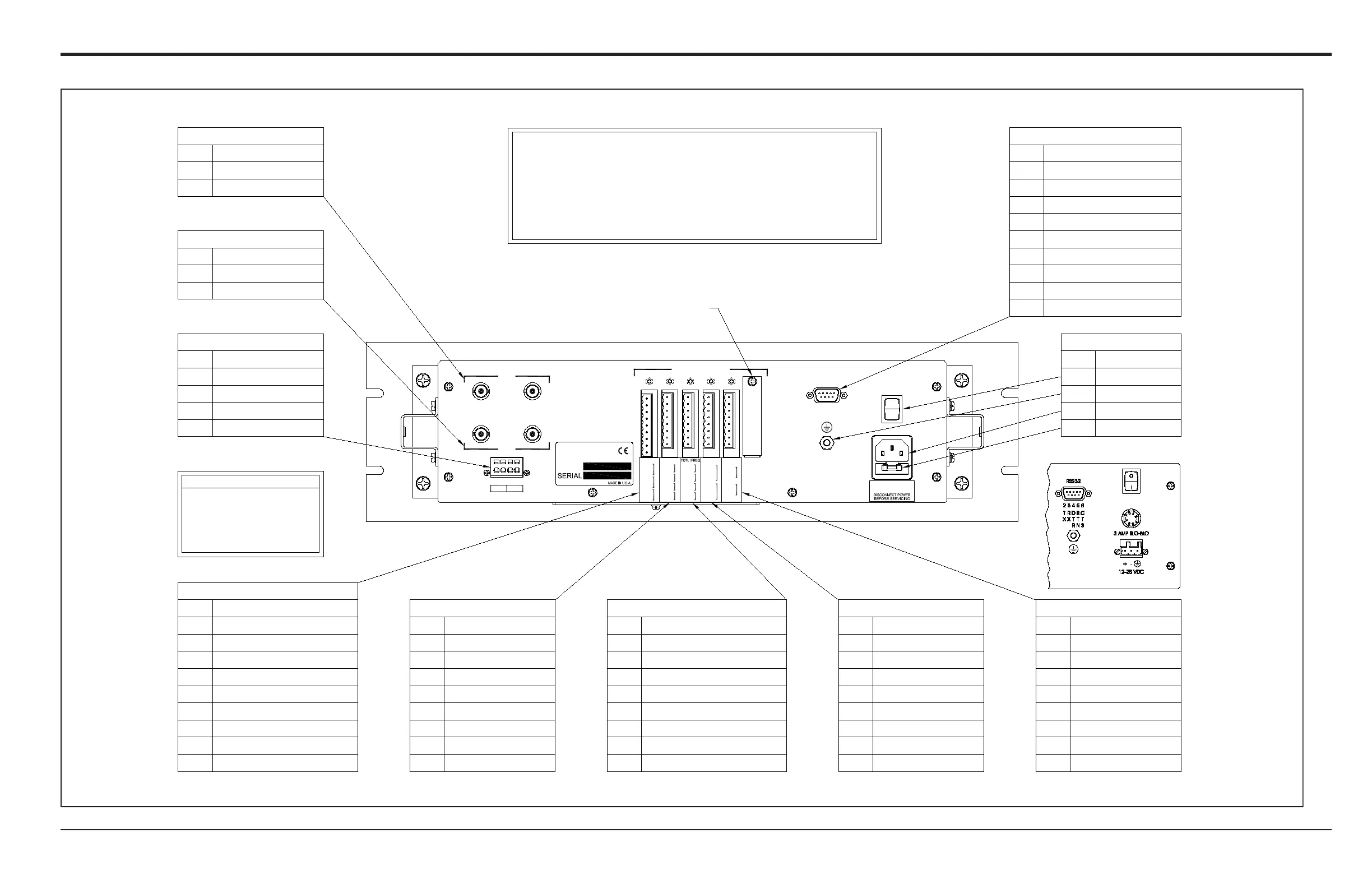
OPTION CARDS
+
CH2
CH1
ANALOG OUT
TRANSDUCER CONNECTIONS
-
+
A
UP
UP
-
B
MODEL
DN
DN
RS232
USE ONLY WITH A 250V FUSE
100 - 120 VAC
FUSE 1 AMP
OFF
ON
Unused
Input A - Common (C)
Input A - SIG(+)
Input B - Common (C)
Input B - Common (C)
Input B - SIG(+)
Unused
Description
Input A - Common (C)
Description
Output A - SIG(+)
Output A - RTN(-)
Output B - SIG(+)
Output B - RTN(-)
0/4-20 mA ANALOG OUTPUTS
Description
CH1 TRANSDUCER
Description
Downstream XDCR
Upstream XDCR
CH2 TRANSDUCER
ON/OFF Switch1
Relay C - Normally Closed (NC)
Relay B - Common (C)
Relay B - Normally C
losed (NC)
Relay C - Normally Open (NO)
Relay C - Common (C)
Relay B - Normally Open (NO)
Relay A - Normally Closed (NC)
Relay A - Common (C)
Relay A - Normally Open (NO)
Power Cord
Earth Ground
1
One option card of each
available type is shown in this
diagram. These cards are not
always installed in the same
slots used for this example.
NOTE
8
9
7
6
5
3
4
2
DescriptionPin #
ALARM RELAYS
3
2
Input A - INHI
Input B - RTN
In
put B - +24V
Input B - INHI
Input B - INLO
Input A - +24V
Input A - INLO
Input A - RTN
0/4-20 mA ANALOG INPUTS
Pin # DescriptionDescriptionPin #
Output B - SIG(+)
Output B - RTN(-)
Output A - SIG(+)
Output A - RTN(-)
Output D - SIG(+)
Output D - RTN(-)
Output C - SIG(+)
Output C - RTN(-)
7
8
6
4
5
2
3
1
7
8
6
4
5
2
3
1
0/4-20 mA ANALOG OUTPUTS
Pin #Pin # Description
Output A - Normally Open (NO)
Output D - Normally Open (NO)
Output C
- Common (C)
Output C - Normally Open (NO)
Output D - Common (C)
Output A - Common (C)
Output B - Common (C)
Output B - Normally Open (NO)
7
8
6
4
5
2
3
1
7
8
6
4
5
2
3
1
TOTALIZER/FREQUENCY OUTPUTS
UP
DN
BNC #
For compliance with the European Union's Low Voltage
Directive, this unit requires an external power
disconnect device such as a switch or circuit breaker. The
disconnect device must be marked as such, clearly visible,
directly accessible and located within 1.8 m (6 ft) of the
Model GF868.
DTR - Data Terminal Ready
RS232 SERIAL PORT (DB9)
POWER INPUT
Description
RX - Receive
3
NOTE:
Item #
5
4
1
2
Pin # Description
TX - Transmit
BNC #
1
3
4
2
Pin #
DN
UP
RTD INPUTS
Fuse4
6
7
8
9
No Connection
Upstream XDCR
Downstream XDCR
CTS - Clear to Send
No Connection
No Connection
RTN - Digital Return
No Connection
Covered Option Card Slot
NC3
3
4
5
6
7
8
NO
C
NC
4
6
5
NO7
NC9
C8
B
C
NO
NO
NO
B
C
D
RTN
SIG
RTN
SIG
RTN
SIG
C
C
C
4
5
3
8
7
6
RTN
INLO
INHI
+24V
4
5
3INLO
RTN
8
7
6
B
D
C
A / OUT
1
2
C2
NO1
A
ALARMS
NO
A
RTN
SIG
C
2
1
2
1
INHI
+24V
A
A / IN
2COM
A
A
NC
NC
COM
+
COM
COM
B
8
3
4
5
7
6
B
+1
RTD IN
REAR-VIEW DC OPTION

 Loading...