Chapter 1. Installation
2 DigitalFlow™ XMT868i Startup Guide
1.3 Site Considerations
Because the relative location of the flowcell and the electronics enclosure is important, use the guidelines in this
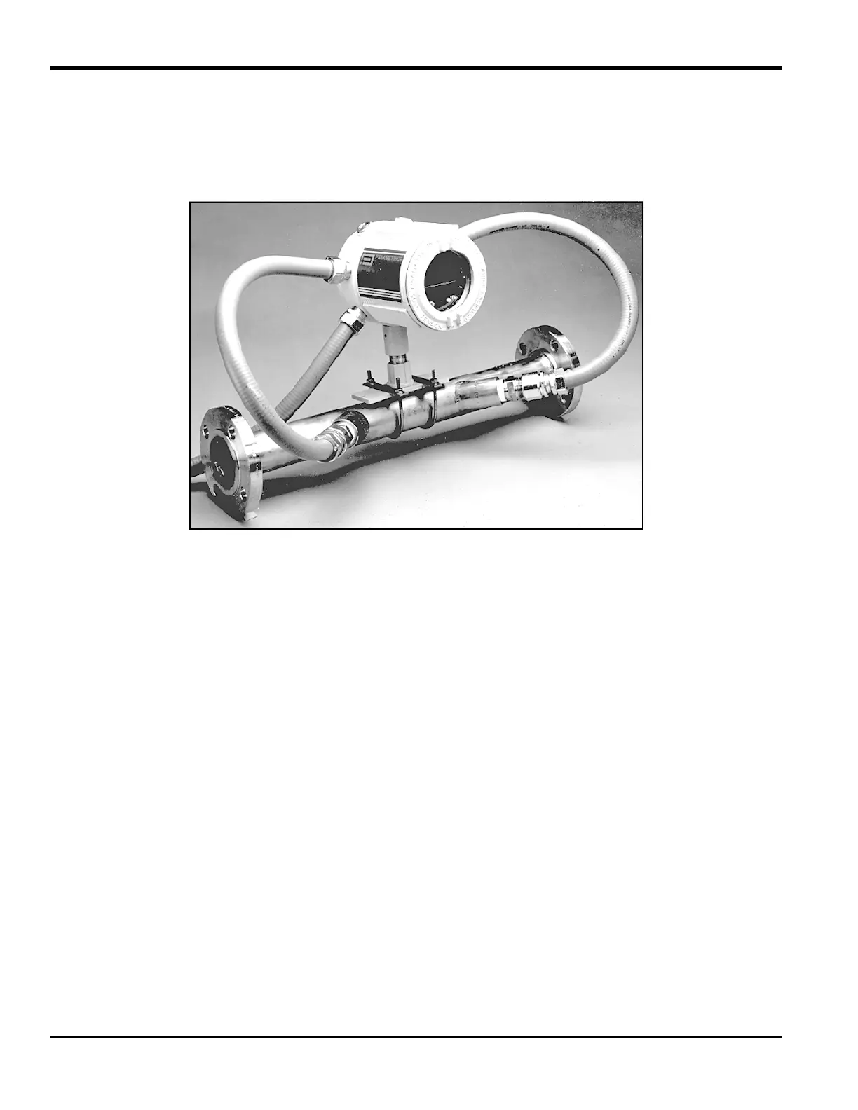
section to plan the XMT868i installation. Figure 1 below shows a typical installation.
Figure 1: A Typical Model XMT868i System
1.3.1 Electronics Enclosure Location
The standard Model XMT868i electronics enclosure is a powder-coated, cast-aluminum, Type-7/4X explosion-proof
enclosure, and an optional stainless-steel enclosure is available. Typically, the enclosure is mounted as close as possible
to the transducers. When choosing a site, make sure the location permits easy access to the electronics enclosure for
programming, maintenance and service.
Note: For compliance with the European Union’s Low Voltage Directive, this unit requires an external power
disconnect device such as a switch or circuit breaker. The disconnect device must be marked as such, clearly
visible, directly accessible, and located within 1.8 m (6 ft) of the unit.
1.3.2 Flowcell Location
Ideally, choose a section of pipe with unlimited access; for example, a long stretch of pipe that is above ground.
However, if the flowcell is to be mounted on an underground pipe, dig a pit around the pipe to facilitate installation of
the transducers.