Chapter 1. Installation
6 DigitalFlow™ XMT868i Startup Guide
1.7 Making Electrical Connections (cont.)
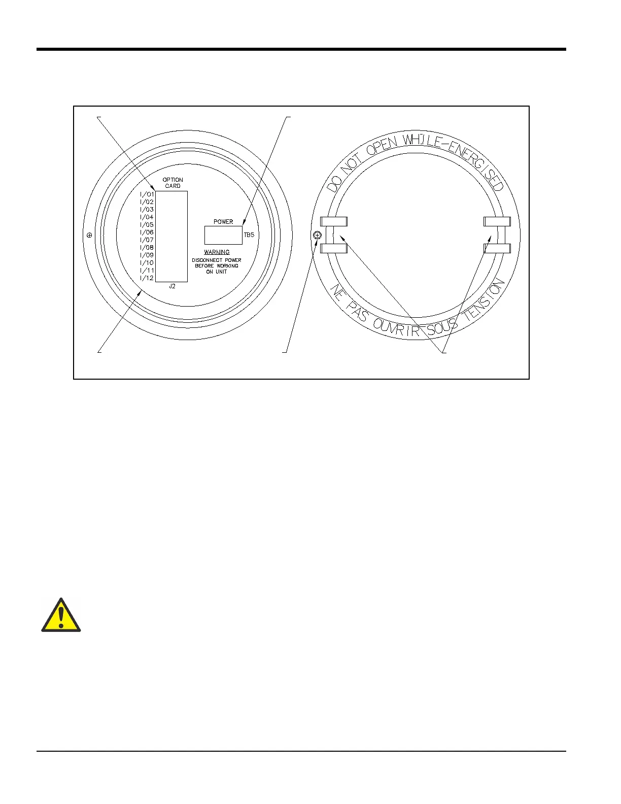
Figure 3: Rear Cover with Connection Labels
1.7.1 Wiring the Line Power
The Model XMT868i may be ordered for operation with power inputs of 100-120 VAC, 220-240 VAC, or 12-28 VDC.
The label on the side of the electronics enclosure lists the meter’s required line voltage and power rating. Be sure to
connect the meter only to the specified line voltage.
Note: For compliance with the European Union’s Low Voltage Directive, this unit requires an external power
disconnect device such as a switch or circuit breaker. The disconnect device must be marked as such, clearly
visible, directly accessible, and located within 1.8 m (6 ft) of the unit.
Note: Only use a Class 2 Rated Power supply for line power connection to a DC instrument.
Refer to Figure 10 on page 23 to locate terminal block
TB5 and connect the line power as follows:
WARNING! Improper connection of the line power leads or connecting the meter to the incorrect
line voltage may damage the unit. It may also result in hazardous voltages at the flowcell and
associated piping as well as within the electronics enclosure.
Slots
Power Connections
Option Card Connections
Label
Set Screw
Inside View Outside View