Chapter 1. Installation
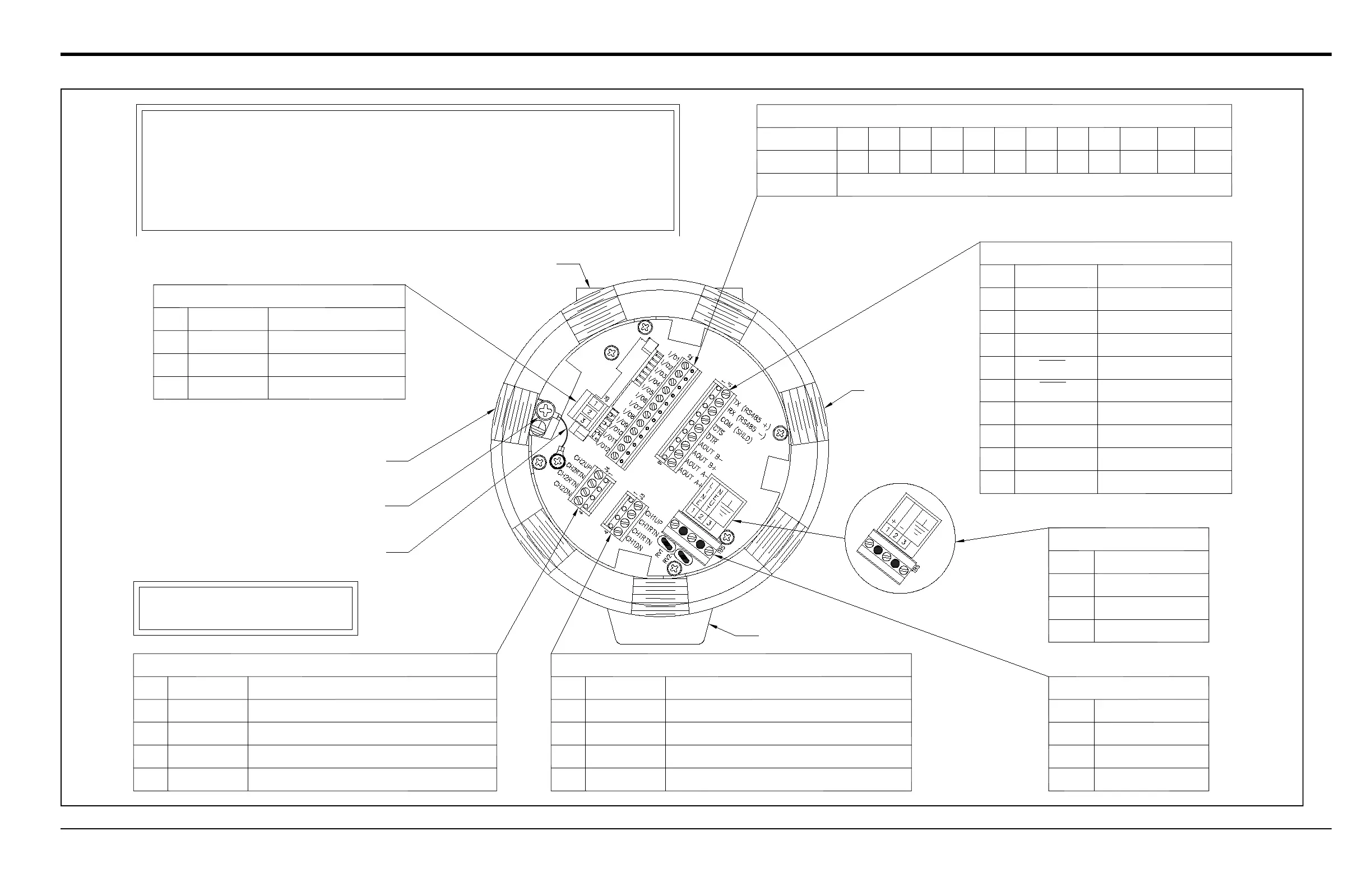
Pin #
1
2
3
Description
Line Power
Line Neutral
Earth Ground
AC POWER INPUT
J1 - RS232/RS485 / 4-20 OUTPUT
Data Terminal Ready
Ground
Clear To Send
Description
Transmit / +
Receive / –
For compliance with the European Union's Low Voltage Directive
(2006/95/EC), this unit requires an external power disconnect device
such as a switch or circuit breaker. The disconnect device must be
marked as such, clearly visible, directly accessible and located
within 1.8 m (6 ft) of the unit.
NOTE:
J4 - CH2 TRANSDUCER CONNECTION (optional)
Upstream Transducer SIG(+)
Downstream Transducer SIG(+)
Upstream Transducer Analog RTN(-)
Downstream Transducer Analog RTN(-)
Description
DC POWER INPUT
Pin #
2
3
1
Description
Line Negative
No Connection
Line Positive
Mounting Boss
Power Cable
Inlet
Conduit Hole (1 of 7)
Grounding Jumper
Protective Conductor Terminal
Nameplate
NOTE: Enclosure is shown from the
rear with the rear cover removed.
Pin #
1
2
3
4
1
4
5
2
3
Pin #
CH2UP
CH2RTN
CH2RTN
CH2DN
Designation
J3 - CH1 TRANSDUCER CONNECTION
Upstream Transducer SIG(+)
Downstream Transducer SIG(+)
Upstream Transducer Analog RTN(–)
Downstream Transducer Analog RTN(-)
DescriptionPin #
1
2
3
4
CH1UP
CH1RTN
CH1RTN
CH1DN
Designation
DTR
RX(RS485–)
TX(RS485+)
CTS
COM (SHLD)
Designation
4-20 Output 2 RTN
4-20 Output 1 SIG
4-20 Output 2 SIG
4-20 Output 1 RTN
6
7
8
9
AOUT B–
AOUT B+
AOUT A–
AOUT A+
J5 - MODBUS CONNECTION
MODBUS +
MODBUS –
N/C
DescriptionPin #
1
2
3
+
–
N/C
Designation
Designation
Description
Pin #
I/O12I/O11I/O10I/O9I/O8I/O7I/O6I/O5I/O4I/O3I/O2I/O1
123456789101112
*See the wiring label inside the rear cover and Figure 1-11.
J2 - INPUT/OUTPUT CONNECTIONS*