Chapter 1. Installation
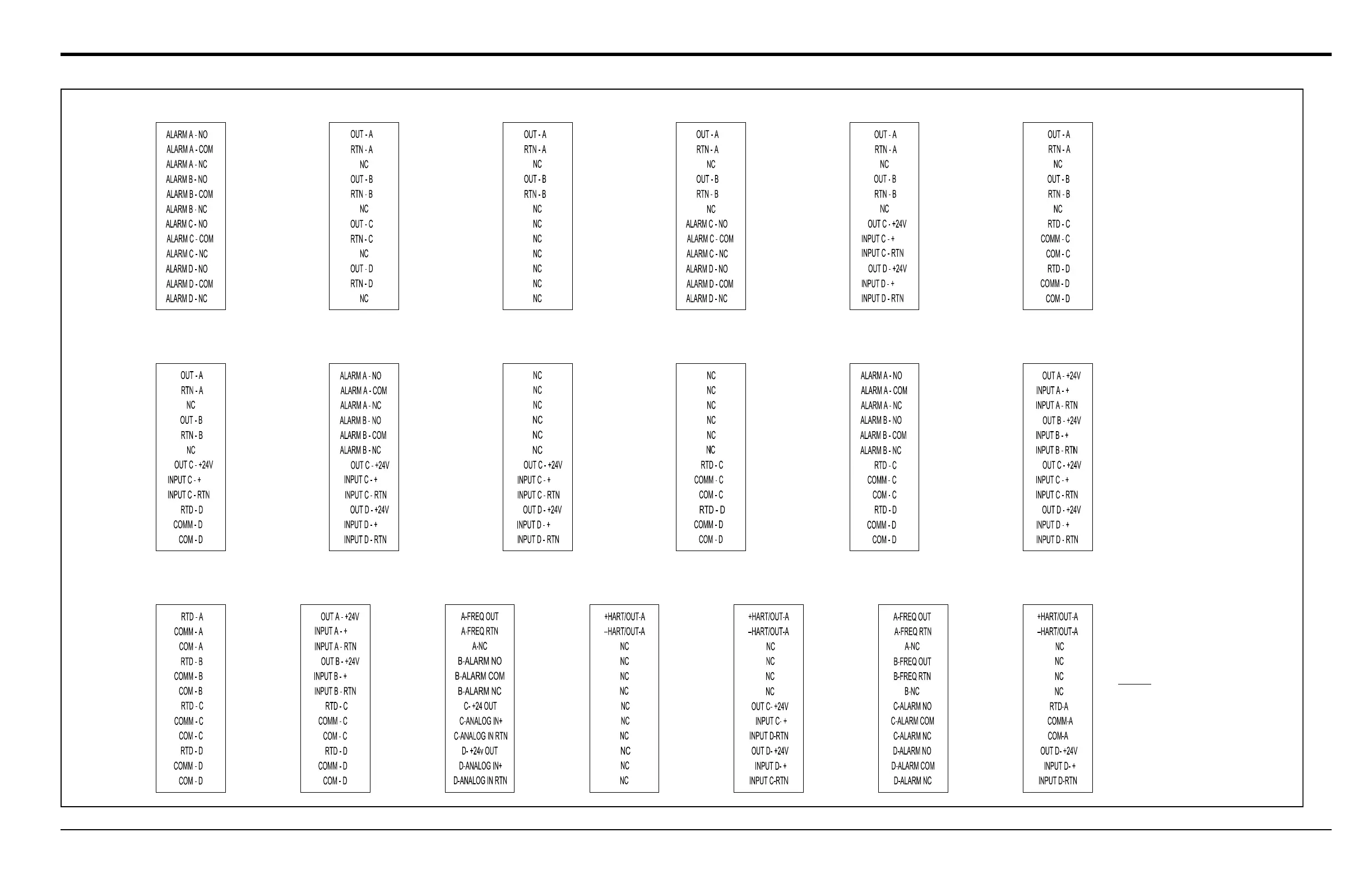
-01 (AA,HH) -02 (FF,TT,FT,CT,CF) -03 (FO,TO,CO) -04 (FA,FH,TA,TH,CA,CH) -05 (CI,TI,FI)
-06 (CR,FR,TR)
-07 (CIR)
-11 (AR,HR)-09 (OI)-08 (AI,HI) -10 (OR) -12 (II)
-13 (RR) -14 (IR)
Pin 1
2
3
4
5
6
7
8
9
10
11
12
11
12
9
10
7
8
2
4
5
6
3
Pin 1
9
11
12
10
7
8
6
5
3
4
Pin 1
2
11
12
9
10
7
8
2
4
5
6
3
Pin 1
9
11
12
10
7
8
6
5
4
3
Pin 1
2
12
11
10
9
8
7
2
4
5
6
3
Pin 1
9
10
12
11
10
11
12
Pin 1
7
8
6
5
4
3
2
9
8
7
Pin 1
2
4
5
6
3
9
11
12
10
7
8
6
5
Pin 1
4
3
2
12
11
10
9
8
7
2
4
5
6
3
Pin 1
9
11
12
10
7
8
6
5
4
3
Pin 1
2
12
11
10
9
8
7
2
4
5
6
3
Pin 1
9
10
12
11
2
Pin 1
3
4
5
6
8
7
7
8
9
10
11
12
Pin 1
3
6
5
4
2
R = RTD Input
A = Standard Alarm
H = Hermetic Alarm
F = Frequency Output
T = Totalizer Output
I = Current Input
C = Current Output
O = Blank/
No Connection
NOTE:
-17 (HART/OI)-15 (FHII) -16 (HART) -18 (F(F)HH)
9
11
12
10
7
8
6
5
3
4
Pin 1
2
9
11
12
10
7
8
6
5
4
3
Pin 1
2
9
10
12
11
Pin 1
7
8
6
5
4
3
2
9
11
12
10
7
8
6
5
Pin 1
4
3
2
-19 (HART/RI)
9
10
12
11
Pin 1
7
8
6
5
4
3
2
 Loading...


