Chapter 3. Operation
52 DigitalFlow™ XMT868i Startup Guide
3.5.1 Programming the LCD (cont.)
8. Scroll to the desired Channel Option from the list in Table 19 below.
9. For each channel, select the desired Measurement Parameter from the list in Table 20 below.
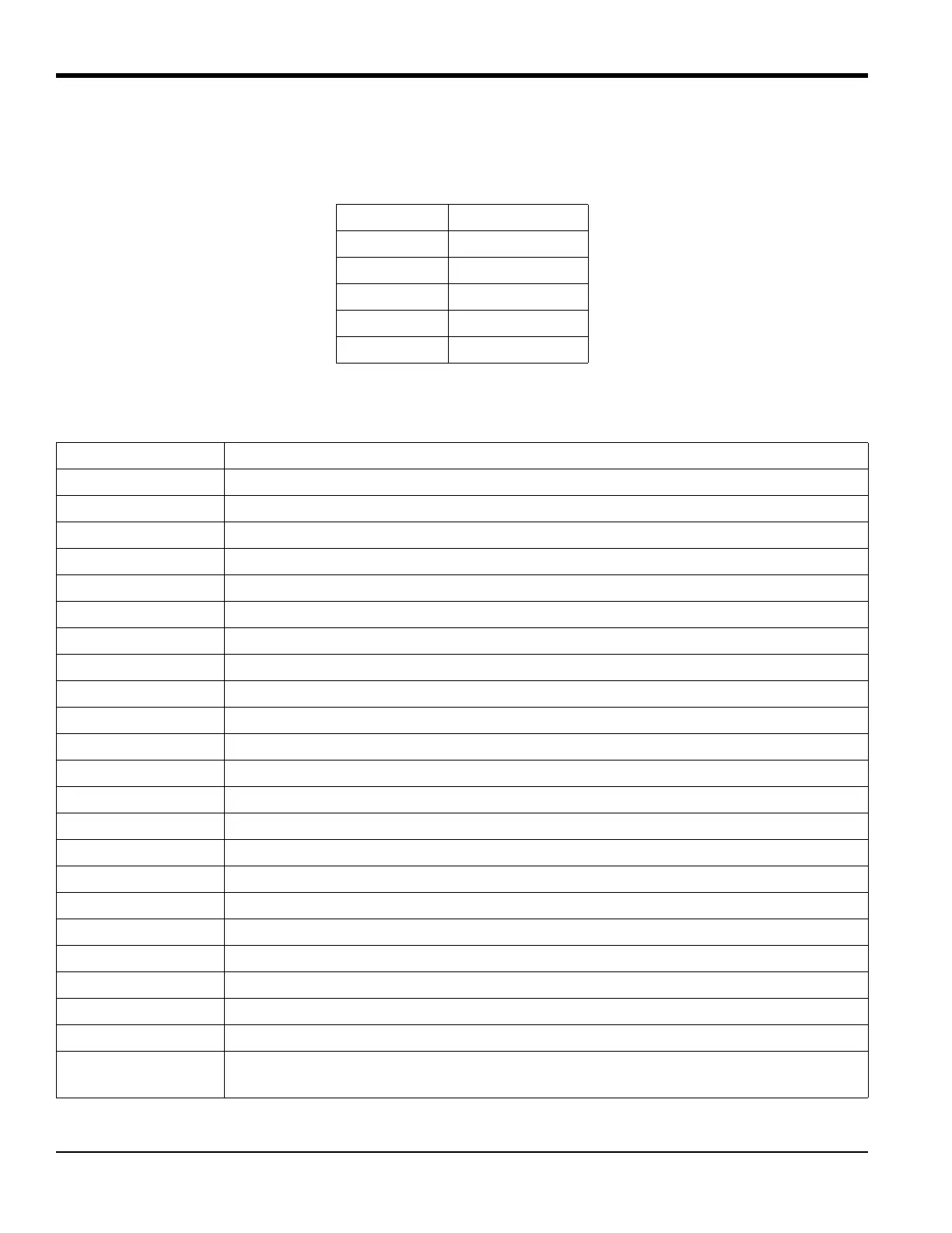
Table 19: Channel Options
Option Description
CH1 Channel 1
CH2 Channel 2
SUM CH1+CH2
DIF CH1-CH2
AVE (CH1+CH2)/2
Table 20: Output Measurement Options
Option Bar Choice Description
VEL
Flow Velocity
VOLUM
Volumetric Flow
+TOTL
Forward Totalized Volume Flow
-TOTL Reverse Totalized Volume Flow
TIME Total Flow Measurement Time
MDOT Mass Flow
+MASS Forward Totalized Mass Flow
-
MASS Reverse Totalized Mass Flow
POWER Energy Flow Power
+ENRG Forward Energy Flow
-ENRG Reverse Energy Flow
SS up Signal strength for the upstream transducer.
SS do Signal strength for the downstream transducer.
Soundspeed Measured speed of sound in the fluid.
DAC up AGC DAC count for upstream gain setting.
DAC do AGC DAC count for downstream gain setting.
T up Upstream ultrasonic signal transit time.
Tdown Downstream ultrasonic signal transit time.
DELTA Transit time difference between upstream and downstream signals.
REYN# Current velocity/reynolds number.
K (RE) K factor, based on the Reynolds number.
PEAK% Percentage of peak (set to +50 by default).
THETA Theta 3 is the angle between the ultrasonic beam and the normal to the pipe wall. It is
calculated from measured transit time and the clamp-on parameters (clamp-ons only).