– 52 –
K6
ORANGE
ORANGE
RED
ORANGE
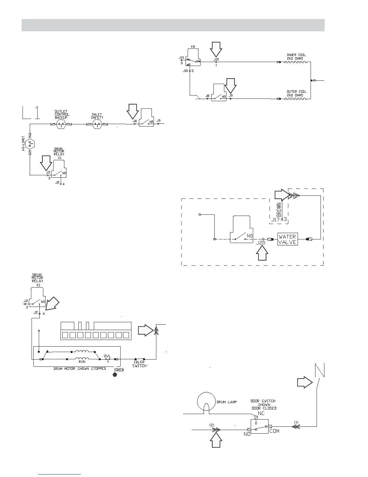
To check thermostats:
1. Disconnect power.
2. Measure resistance between J2 pin 3 and J8.
Note: If all thermostats are intact, reading should be
0
Strip Circuit
To check belt switch:
1. Disconnect power.
2. Measure resistance between J2 pin 4 and plug.
Note: If belt switch and motor are intact, reading
should be 3
5
6
8
7
G
8
G
6
7
4
5
2
3
1
TAB SEQUENCE
DRUM MO TOR
CONNEC TOR
GE
BROWN
PINK
GR AY
BLACK
BROWN
7
J1 7
START
To check heaters:
1. Disconnect power.
2. Measure resistance between J9 and J10.
Note: If both heaters are intact, reading should be
40
K6
ORANGE
WHITE
BLUE
PURPLE
To check water valve:
1. Disconnect power.
2. Measure resistance between J20 and plug.
Note: The resistance of the valve coil should read
400
STEAM
K9
WHEN USED
J2
4
J21
BLACK
RED
BROWN
To check door switch:
1. Disconnect power.
2. Measure resistance between J1 pin 3 (neutral)
and plug.
Note: The resistance should read 0 with the door
closed and ∞ with the door open.
BLACK
WHITE
BROWN
WHITE
WHITE
BROWN
J1
3