– 34 –
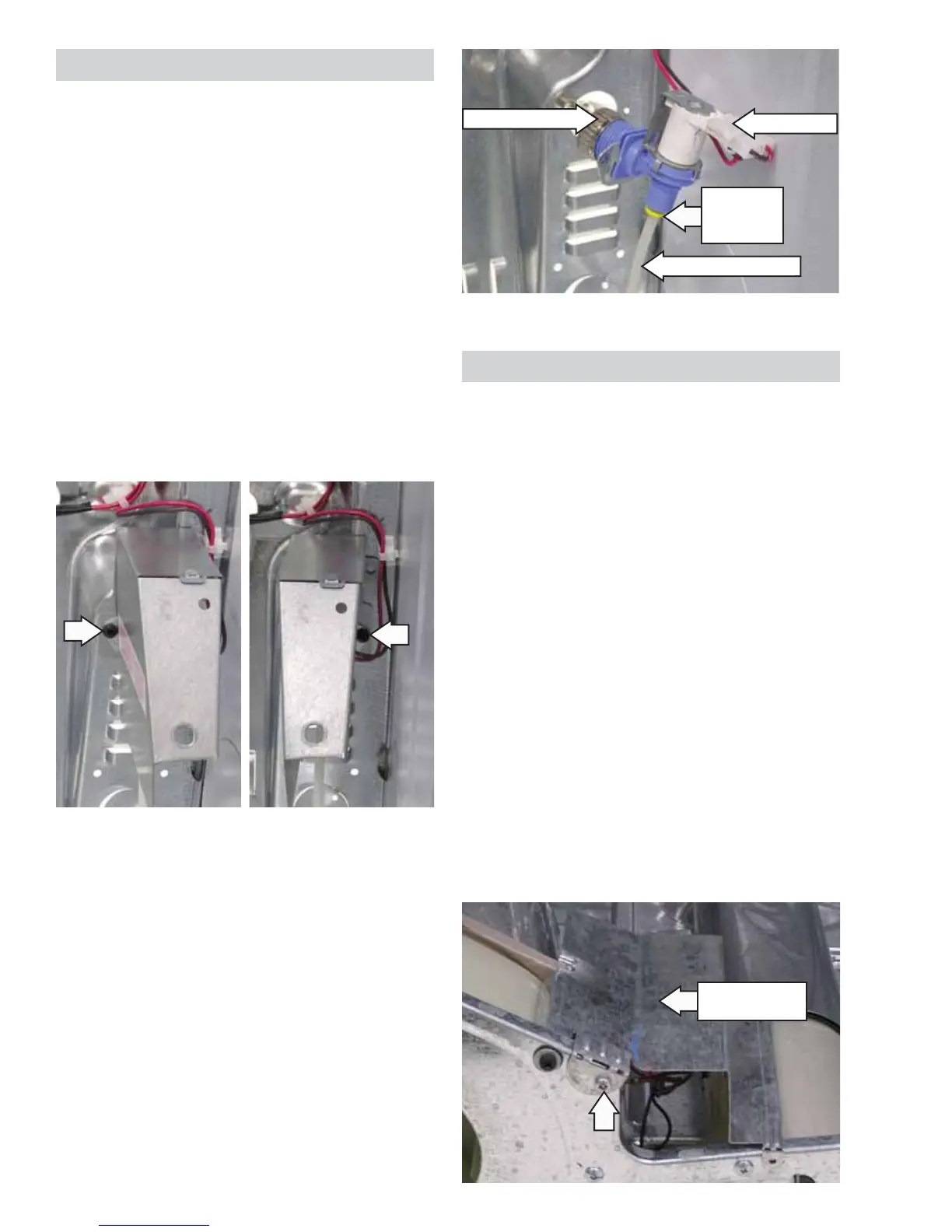
Water Inlet Valve
The water inlet valve is located inside the cabinet
at the bottom right hand corner. The water valve is
enclosed under a metal cover. The cover is attached
to the dryer with a Phillips-head screw and a tab
located at the bottom.
The valve has an approximate resistance value of
406 .
Operation of the water inlet valve can be checked
by using service test mode T07. (See Service Test
Mode.)
To replace the inlet water valve:
1. Remove the drum. (See Drum.)
2. Remove the 2 Phillips-head screws that hold the
cover to the cabinet and remove the cover by
lifting up and out.
Note: In the following steps, capture any residual
water that may escape from the valve, fi ll hose, and
tubing.
3. Disconnect the water inlet hose.
4. Disconnect the coil wiring.
5. Press the John Guest connector collar and
remove the water outlet tubing.
Water Inlet Hose
Disconnect
Water Outlet Tubing
John Guest
Connector
Collar
Motor and Blower Wheel
The motor is a single-speed, dual-shaft, 1/4-hp,
1725-rpm motor with an automatic reset overload
protector. The overload protector is an internal
component of the motor and cannot be replaced
separately. The motor contains a centrifugal switch
that serves three purposes: It disengages the motor
start winding (6), engages the motor run winding (8),
and closes the circuit contacts (1 to 3) for the heat
source.
The blower wheel is held to the motor shaft with a
15/16-in. (24-mm) molded nut.
Motor resistance values:
Start winding = 2.3 ohms
Run winding = 2.3 ohms
To remove the motor:
1. Disconnect power to the unit.
2. Remove the drum. (See
Drum.)
3. Remove the Phillips-head screw and the
thermostat moisture shield from the front frame.
Thermostat
Moisture Shield
(Continued Next Page)