– 35 –
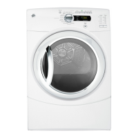
4. Remove the Phillips-head screw and the outlet
control backup thermostat from the blower
housing.
(Continued Next Page)
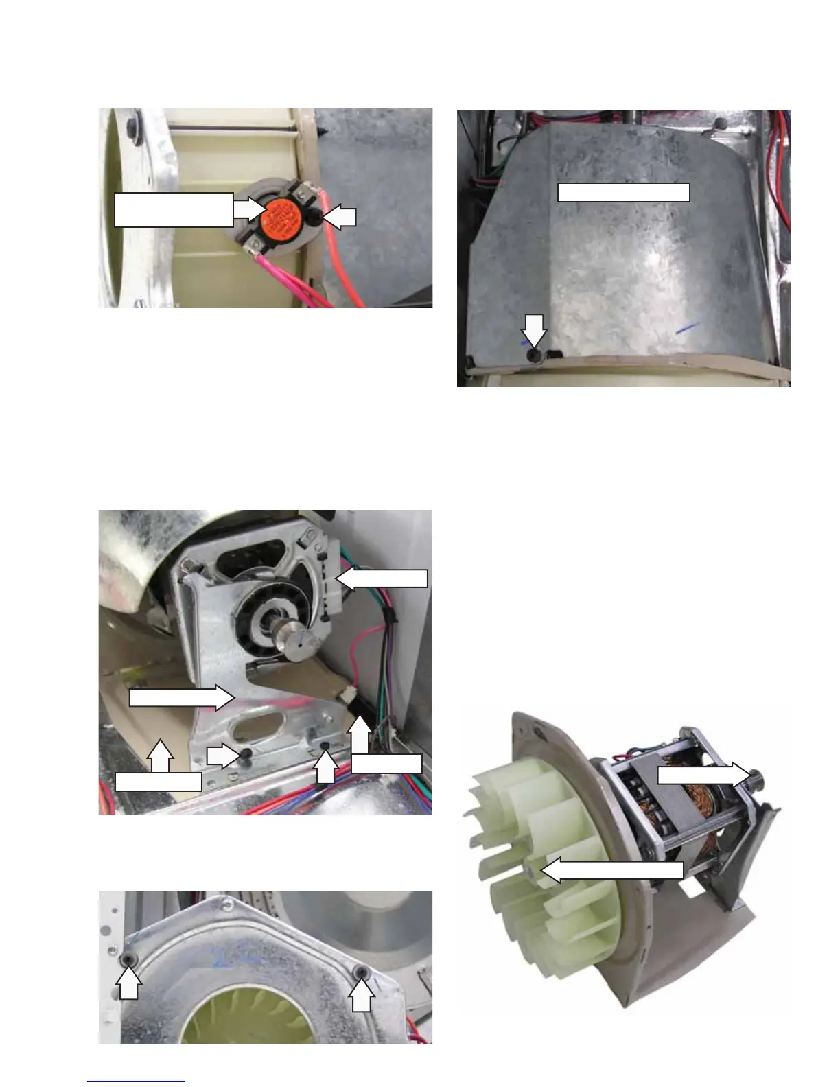
5. Remove the idler pulley assembly from the
motor bracket. (See
Idler Assembly)
6. Disconnect the motor wire harness.
7. Disconnect the wires attached to the belt switch.
8. Remove the single vertical and single horizontal
Phillips-head screws that attach the motor
bracket and motor support to the chassis.
9. Remove the 2 Phillips-head screws and 2
washers that hold the top of the motor base
plate to the blower housing.
Disconnect
Belt Switch
Motor Support
Motor Bracket
Outlet Control
Backup Thermostat
Motor Moisture Shield
11. Raise the rear of the motor bracket to clear the
tab protruding from the bottom of the chassis.
Slide the motor bracket back until the bracket
tabs clear the slots in the chassis. Remove the
motor and blower wheel assembly from the
chassis.
Note: When installing the motor and blower wheel
assembly, ensure that the 2 rear tabs on the motor
bracket are inserted into the slots in the motor
support, and the 2 front tabs on the motor bracket
are inserted into slots provided in the chassis.
12. Hold the motor shaft from turning and use a
15/16-in. (24-mm) socket to remove the blower
wheel from the motor shaft.
15/16-in. Molded Nut
Motor Shaft
10. Remove the Phillips-head screw, then disengage
the motor moisture shield from the motor
bracket.