GE HEALTHCARE
DIRECTION 5162630, REVISION 3 LOGIQ™ S6 SERVICE MANUAL
Section 5-7 - Air Flow Control 5-41
5-7-3 Fans
The scanner contains the nine fans at the following positions for producing an air flow.
- Three fans: At the bottom of the NEST Assy for air flow path C
- One fan (PC box-inlet): On the bottom of the PC Box for air flow path D
- Two fan (PC box-outlet): On the upper of the PC Box for air flow path D
- One fan: In the ATX PS of the PC Box for air flow path D
- One fan: On the LV unit for air flow path B
- One fan: On the HV unit for air flow path B
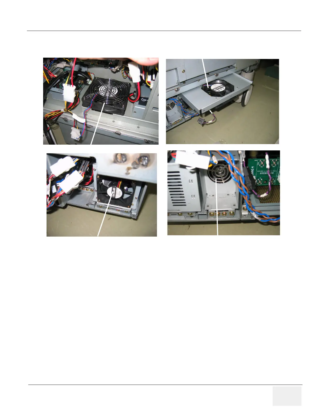
Figure 5-72 Fans
One fan for PC box
Three fans for Nest Assy
One fan for LV unit
One fan for HV unit
 Loading...


