Marquette Hellige GmbH MAC 1100/1200 V 1.1 Page 17
227 492 20 D - 0002
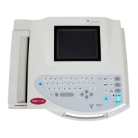
2.3.7 LCD graphics display interface
For the LCD interface to the ¼ VGA monochrome LCD interface, the internal LCD
controller of the MPC821 is used.
Controller Interface:
For the digital control signals, delivered from the MPC821, only an output driver is
required.
LCD Power Supply:
The LCD power supply VEE of -23V is generated from the +5V logic supply. The
generation starts after HRESET_ becomes inactive to ensure that the logic supply of
+5V first is applied to the display.
Adjusting Contrast:
Contrast adjustment of the Display is accomplished with the contrast voltage V0. The
level of V0 is controlled with the PWM signal BLCD_CONTR from the timer module
of the MPC821. In addition, the contrast voltage is temperature compensated.
Backlight:
The LCD backlight converter for the CCFL tube is located on the PCB Control
CS_CI too. The backlight converter is generated from the +5V logic power supply.
The signal BLCD_ENBA switches the backlight on or off.
The user can define the backlight active time in the configuration menu.
2.3.8 Keypad interface
The keypad interface contains the control register for 8 keypad columns and the
receiving register for 7 keypad rows, and the control signals for the status LEDs:
LED_LIN, LED_BATT, LED_START and LED_STOP.
Using the matrix of 8 x 7, up to 56 keypads can be detected.
Identification of the key pressed is as follows:
The controller activates a column, activation is via low-level, then the row-register is
read to identify the pressed key by a low-level. This procedure is repeated with the
next column, till all columns have been activated.

 Loading...