Marquette Hellige GmbH MAC 1100/1200 V 1.1 Page 24
227 492 20 D - 0002
In Circuit Programming Port
With the In Circuit Programming Port, both CPLDs can be programmed or updated in
a Daisy Chain queue.
Connector denotation: ISP/
Type: male connector, 2x 5-pin, 180 °, pin 4: coding pin
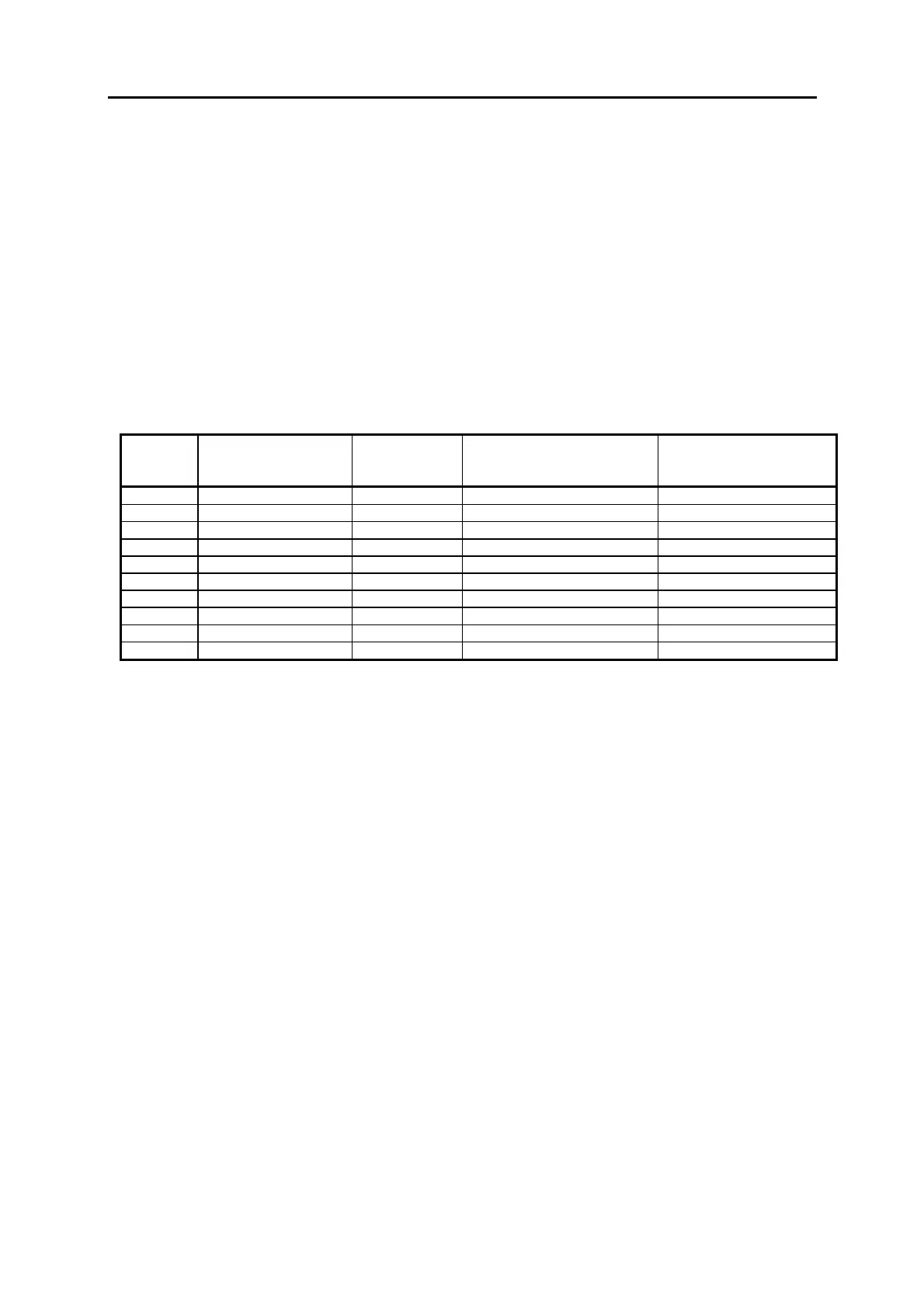
The function of the individual pins is given in the following table . The definition as an
input/output is seen with reference to PCB Control CS_CI.
ISP/
Pin
Number
Signal input/output Function Definition
1 ISP SCLK In
ut Serial ISP Clock
2GND Lo
ic Ground
3ISPMODE In
ut ISP Mode Select
4 Code Codin
in
5 ISP EN In
ut Enable In Circuit
ro
ram. “0“: ISP enable
6 ISP SDI In
ut Serial Data In
7 ISP SDO Out
ut Serial Data Out
8 +5V Lo
ic su
l
9NC
10 NC
.
2.5.2.8 Interface to PCB Modem Supply CS_M
The interface to PCB Modem Supply CS_M is realized by the connectors MO_SU/
and RS232_E/.
MO_SU/ delivers the voltage +26,5 for the modem supply generation, RS232_E/
receives the generated modem voltage +8V for the PCB Control CS_CI.
Connector denotation: MO_SU/
Type: multipoint connector 1 X 3 pin., 180°,
reverse terminal protection, MODU II
The function of the individual pins is given in the following table . The definition as an
input/output is seen with reference to PCB Control CS_CI.

 Loading...


