Marquette Hellige GmbH MAC 1100/1200 V 1.1 Page 21
227 492 20 D - 0002
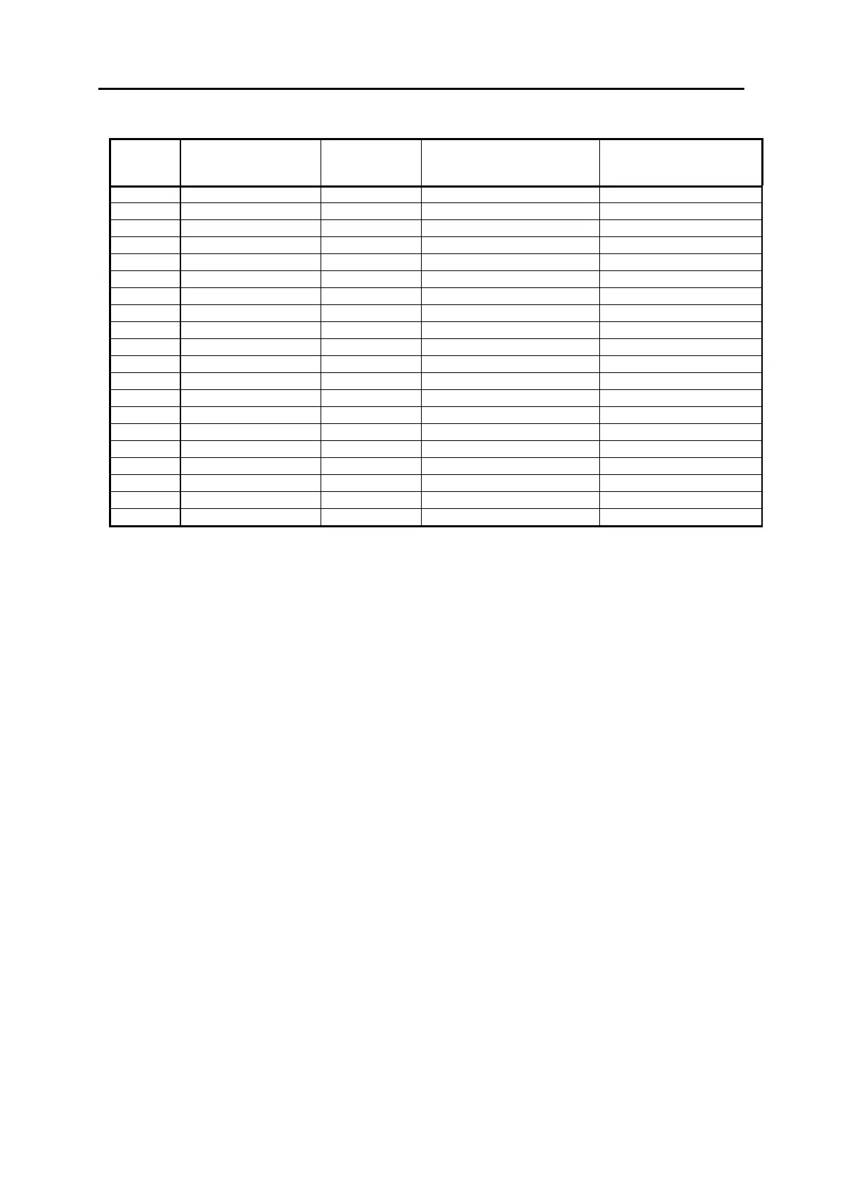
BATT/
Pin
Number
Signal input/output Function Definition
1 +24V Out
ut Su
l
batter
char
in
2 +24V Output Suppl
batter
char
in
3 +24V Output Suppl
batter
char
in
4 Code Codin
Pin
5NC
6 GND24V common Ground
7 GND24V from power suppl
8 GND24V after ferrite decouplin
9 GND24V
10 +UBATT Input Batter
volta
e
11 +UBATT Input Batter
volta
e
12 +UBATT Input Batter
volta
e
13 +UBATT Input Batter
volta
e
14 +UBATT_ME Input
Battery measuring output
15 Code Codin
Pin
16 +5V_L Output + 5V suppl
17 NC
18 BATT_OPT
Input Status option batter
“0“: option active
19 LOAD_OFF Output Char
in
reduction
“1“: reduced charging
20 NC
2.5.2.3 Interface to the LCD Graphics Display
The interface to the LCD graphics display provides the LCD data signals, the display
supply voltages +5V and VEE, the display contrast voltage V0 and the display on/off
control signal.
Connector denotation: HOS/
Type: Foil connector, 14- pin, zero power insertion, 180°
The LCD supply voltage VEE can be measured at R 731 on the PCB Control CS_CI,
the LCD contrast voltage can be measured at R 730. Both levels of these voltages
depend on the contrast selected.
The voltage supply for the CCFL tube of the display is provided separately via the
connector BL/.
Caution! Do not touch! High AC voltage!
2.5.2.4 Interface to the keypad
The interface to the keypad is realized with the connector KEYB/. It contains the
signals for the keypad rows and columns, the supply and the control signals for the
status LEDs of the keypad. The foil connecting cable is part of the keypad itself.

 Loading...


