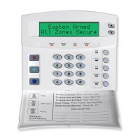
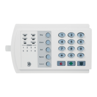
NX-8E CONTROL
25
LOCATION 47 - AUXILIARY OUTPUT #1, EVENT AND TIME (2 segments, numerical data)
Segment 1: Use the chart on page 25 to select the event that will activate Auxiliary Output 1.
Segment 2: Program the timing from 0-255 (minutes or seconds, depending on data programmed in
Segment 1, Location 46). Programming a "0" makes the output follow the event.
LOCATION 48 - AUXILIARY OUTPUT #2, EVENT AND TIME (2 segments, numerical data)
Segment 1: Use the chart on page 25 to select the event that will activate Auxiliary Output 2.
Segment 2: Program the timing from 0-255 (minutes or seconds, depending on data programmed in
Segment 2, Location 46). Programming a "0" makes the output follow the event.
LOCATION 49- AUXILIARY OUTPUT #3, EVENT AND TIME (2 segments, numerical data)
Segment 1: Use the chart on page 25 to select the event that will activate Auxiliary Output 3.
Segment 2: Program the timing from 0-255 (minutes or seconds, depending on data programmed in
Segment 3, Location 46). Programming a "0" makes the output follow the event.
LOCATION 50- AUXILIARY OUTPUT #4, EVENT AND TIME (2 segments, numerical data)
Segment 1: Use the chart on page 25 to select the event that will activate Auxiliary Output 4. .
Segment 2: Program the timing from 0-255 (minutes or seconds, depending on data programmed in
Segment 4, Location 46). Programming a "0" makes the output follow the event.
Table XI-1 AUXILIARY OUTPUT EVENT SELECTION
DATA EVENT DATA EVENT DATA EVENT
0
/
Burglary Alarm
18
Entry
36
Telephone Line Fault
1
/
Fire Alarm
19
Exit
37
Program Mode
2
/
24 Hour Alarm
20
Entry or Exit
38
Download In Process
3
/
Trouble Alarm
21
Armed State
39
Ground Fault
4
/
Tamper Alarm
22
Disarmed State
40
Short Circuit (Over-current)
5
Yelping Siren (Burglary)
23
Ready
41
Box Tamper
6
Temporal Siren (Fire)
24
Not Ready
42
Siren Tamper
7
Any Siren
25
Fire
43
Any Open
8
Any Bypass
26
Fire Trouble
44
Any Short
9
AC Fail
27
Chime
45
Any Fault (Open/ Short on
Non-Fire Zone)
10
Low Battery
28
/
Expander Trouble
46
/
Any Alarm
11
/
Duress
29
Dynamic Battery Test Time
47
Beeping Keypad
12
/
Aux 1 Keypad Zone
30
Open Period
48
/
Code Entry (See note below)
13
/
Aux 2 Keypad Zone
31
Closed Period
49
˜
/
Key FOB Function 1
14
/
Panic Keypad Zone
32
Listen-In
50
˜
/
Key FOB Function 2
15
Keypad Tamper
33
Line Seizure
69
Forced Door Alarm
16
/
Autotest
34
Ground Start
70
Forced Door Restore
17
Alarm Memory
35
Fail To Communicate
˜ Events 49 & 50 require NX-408, NX-416, or NX-448 wireless receivers to operate.
/ If set to follow condition, these events will be 1 second.
Notes: When Event 48 is programmed, it is possible to program a user code's authorization to select which output(s)
a particular code will activate. When LED 8 is on for an authorization, then LEDs 1- 4 correspond to that code
activating outputs 1 - 4 respectively. (See programming the LED keypads on page 8.)
 Loading...
