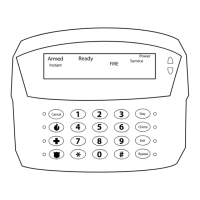
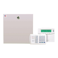
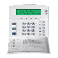
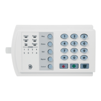
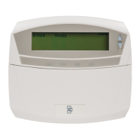
NX-8E CONTROL
71
XVII. APPENDIX 3
EXPANDER NUMBERS FOR REPORTING EXPANDER TROUBLE
The tables below list the device numbers that will be reported for trouble conditions.
Device Device # reported
NX-8E Control Panel 0 See page 69 for possible report codes.
NX-534E Two Way Listen-In 64
NX-540E “Operator” 40
NX-591E Cellemetry Interface 76
NX-870E Fire Supervision 9
KEYPADS
KEYPAD PART 1 PART 2 PART 3 PART 4 PART 5 PART 6 PART 7 PART 8
1 192 193 194 195 196 197 198 199
2 200 201 202 203 204 205 206 207
3 208 209 210 211 212 213 214 215
4 216 217 218 219 220 221 222 223
5 224 225 226 227 228 229 230 231
6 232 233 234 235 236 237 238 239
7 240 241 242 243 244 245 246 247
8 248 249 250 251 252 253 254 255
HARDWIRE EXPANDER (NX-216E)
Starting zone number Expander # reported
Starting zone number Expander # reported
Zone 09 (All switches off) 22 Zone 97 (Switches 3 & 4 on) 100
Zone 09 (Switch 1 on) 23 Zone 105 (Switches 1, 3 & 4 on) 101
Zone 17 (Switch 2 on) 16 Zone 113 (Switches 2, 3 & 4 on) 102
Zone 25 (Switches 1 & 2 on) 17 Zone 121 (Switches 1, 2, 3 & 4 on)
103
Zone 33 (Switch 3 on) 18 Zone 129 (Switch 5 on) 104
Zone 41 (Switches 1 & 3 on) 19 Zone 137 (Switches 1 & 5 on) 105
Zone 49 (Switches 2 & 3 on) 20 Zone 145 (Switches 2 & 5 on) 106
Zone 57 (Switches 1, 2 & 3 on)
21 Zone 153 (Switches 1, 2 & 5 on) 107
Zone 65 (Switch 4 on) 96 Zone 161 (Switches 3 & 5 on) 108
Zone 73 (Switches 1 & 4 on) 97 Zone 169 (Switches 1, 3 & 5 on) 109
Zone 81 (Switches 2 & 4 on) 98 Zone 177 (Switches 2, 3 & 5 on) 110
Zone 89 (Switches 1, 2 & 4 on)
99 Zone 185 (Switches 1, 2, 3 & 5 on)
111
REMOTE POWER SUPPLY (NX-320E) WIRELESS RECEIVER (NX-448E)
Switch Setting Address
Switch Setting Expander # reported
All switches off 84
All switches off 35
Switch 1 on 85
Switch 1 on 36
Switch 2 on 86
Switch 2 on 37
Switch 1 & 2 on 87
Switches 1 & 2 on 38
Switch 3 on 88
Switch 3 on 39
Switch 1 & 3 on 89
Switches 1 & 3 on 32
Switch 2 & 3 on 90
Switches 2 & 3 on 33
Switches 1, 2, & 3 on 91
Switch 1, 2 & 3 on 34
OUTPUT MODULE (NX-508E)
Switch Setting Address Switch Setting Address
Switch 1 & 2 on 24 Switch 1,2,&3 on 28
Switch 3 on 25 All switches off 29
Switch 1 & 3 on 26 Switch 1 on 30
Switch 2 & 3 on 27 Switch 2 on 31
 Loading...
