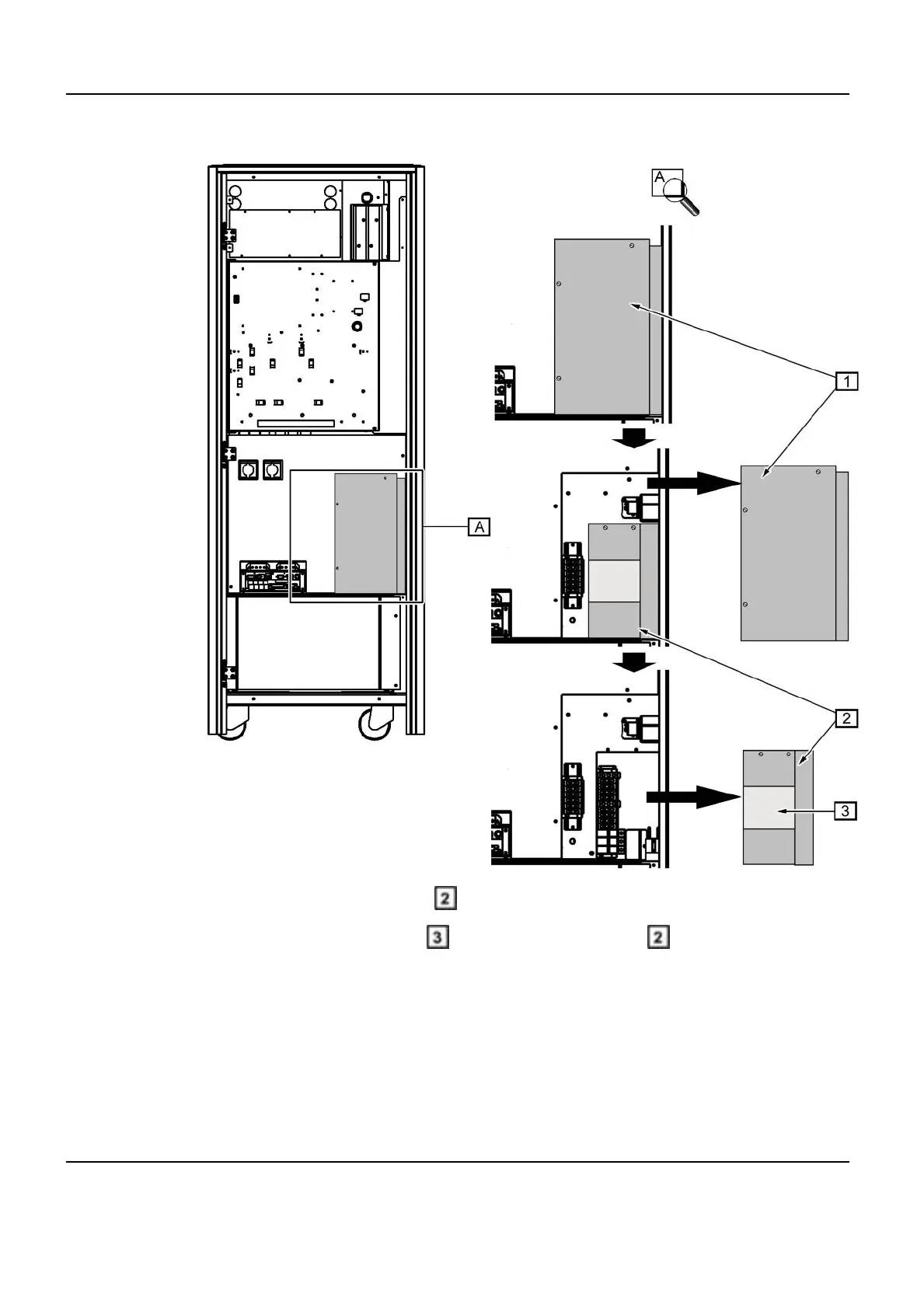
Illustration 7-4:
b.
Remove the protection panel ( , Illustration 7-4).
c.
Remove the metallic window
from the protection panel (Illustration 7-4).
d. The power cable shall enter the UPS by the bottom right hand side entry:
i. Remove RHS UPS cover (remove two top screws make two bottom
screws loose),
ii. Remove bottom cover plate.
Optima IGS 320, Optima IGS 330 Pre-Installation Manual
Direction 5537562-1-1EN, Revision 3
198 1 PIST0021 - US Fluoro UPS and PDB connection
 Loading...


