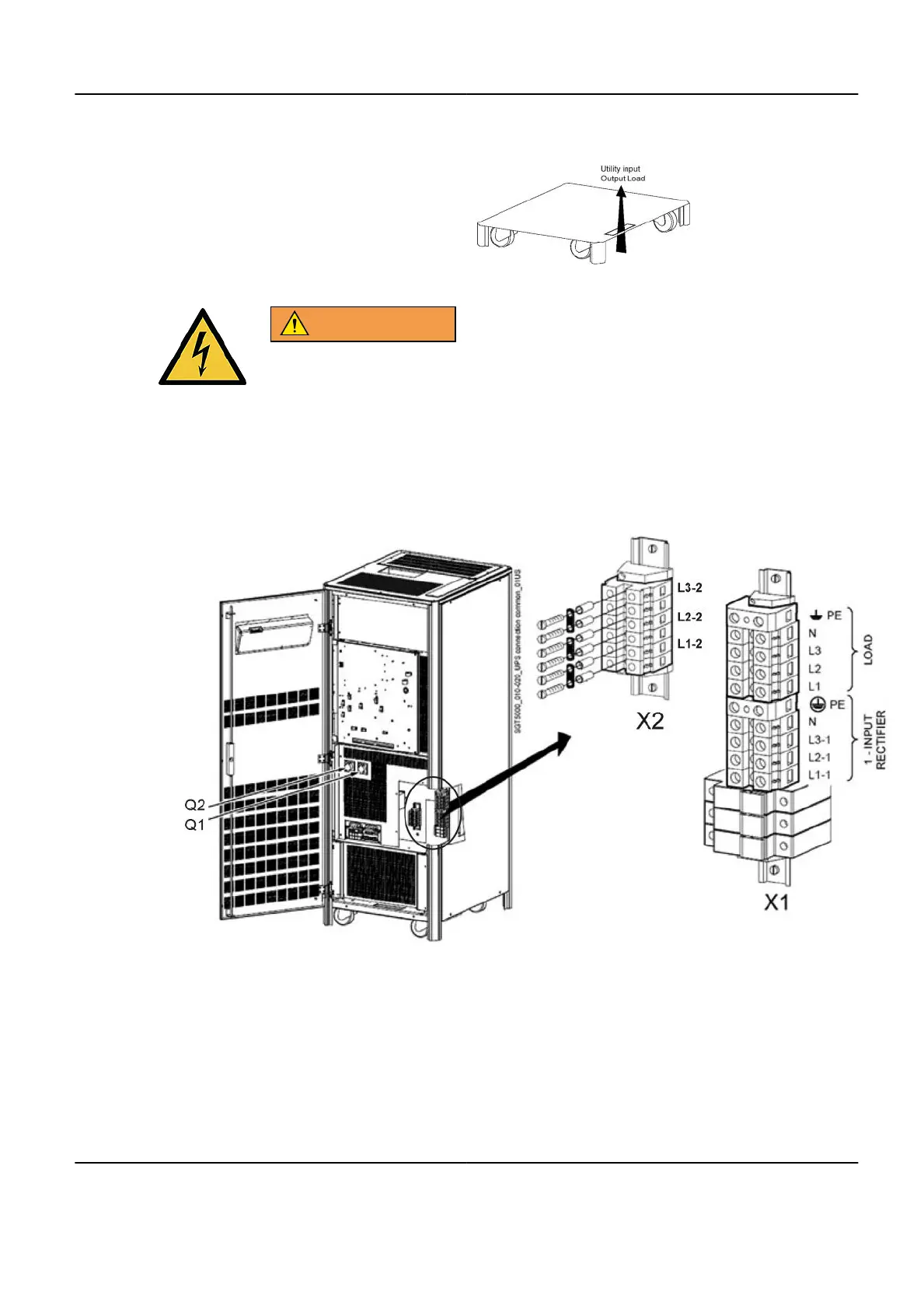
Illustration 7-5:
iii. Drill a hole in the bottom cover plate for cable access.
WARNING
RISK OF ELECTRIC SHOCK
HIGH VOLTAGE PRESENT
THE FLUORO UPS REQUIRES COMMON POWER INPUT FOR
RECTIFIER AND BYPASS . JUMPERS SHALL BE KEPT.
e. Check the jumpers linking the terminals L1-2, L2-2 and L3-2, are properly installed.
Illustration 7-6:
f. Connect the Fluoro UPS rectifier input cable from PDB CB5 as follows (Illustration
7-6):
•
Rectifier input phase 1 to X1-L1-1 terminal,
•
Rectifier input phase 2 to X1-L2-1 terminal,
•
Rectifier input phase 3 to X1-L3-1 terminal,
Optima IGS 320, Optima IGS 330 Pre-Installation Manual
Direction 5537562-1-1EN, Revision 3
Chapter 7 Appendix 199
 Loading...


