Appendix B - Settings and Signals
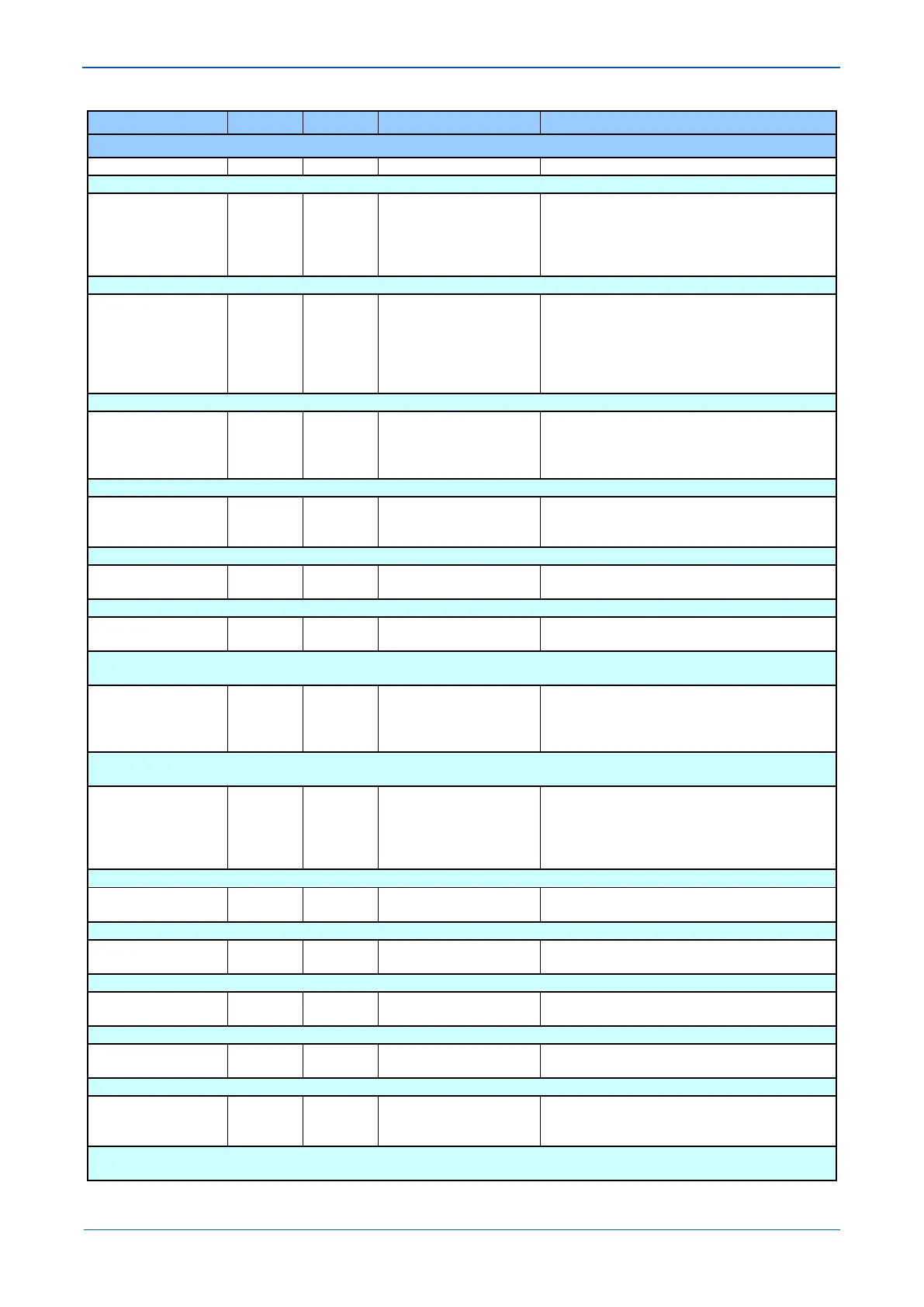
MENU TEXT COL ROW DEFAULT SETTING AVAILABLE OPTIONS
DESCRIPTION
RP2 Protocol 0E 81 Courier
Courier
IEC870-5-103
Modbus
DNP 3.0
RP2 versions only. Indicates the communications protocol that will be used on the rear communications port.
RP2 Card Status 0E 84
Card Not Fitted
EIA232 OK
EIA485 OK
K Bus OK
RP2 versions only. Displays the status of the card in RP2
RP2 Port Config 0E 88 EIA232 (RS232)
EIA485 (RS485)
K-Bus
RP2 versions only. This cell defines whether an electrical EIA(RS)232, EIA(RS)485 or KBus is being used for communication.
RP2 Comms Mode 0E 8A IEC60870 FT1.2
10-bit no parity
RP2 versions only. The choice is either IEC 60870 FT1.2 for normal operation with 11-bit modems, or 10-bit no parity.
RP2 Address 0E 90 255
From 0 to 255 in steps of 1
[Unsigned Integer (16 bits)]
RP2 versions only. This cell sets the unique address for the IED such that only one IED is accessed by master station software.
RP2 InactivTimer 0E 92 15
From 1 to 30 in steps of 1
[Courier Number (time-minutes)]
RP2 versions only. This cell controls how long the IED will wait without receiving any messages on the rear port before it reverts to its default
state, including resetting any password access that was enabled.
RP2 Baud Rate 0E 94 19200 bits/s
19200 bits/s
38400 bits/s
RP2 versions only. This cell controls the communication speed between IED and master station. It is important that both IED and master
station are set at the same speed setting.
NIC Protocol 0E A0 DNP 3.0
UCA 2.0 GOOSE
IEC61850
DNP3.0
DNP 3.0 over Ethernet versions only. Indicates that DNP 3.0 will be used on the rear Ethernet port.
IP Address 0E A1 0.0.0.0
DNP 3.0 over Ethernet versions only. Indicates the IP address of the IED
Subnet Mask 0E A2 0.0.0.0
DNP 3.0 over Ethernet versions only. Indicates the Subnet address
NIC MAC Address 0E A3 Ethernet MAC Address
NIC MAC Address
[ASCII Text (17 chars)]
DNP 3.0 over Ethernet versions only. Indicates the MAC address of the rear Ethernet port.
Gateway 0E A4 0.0.0.0
DNP 3.0 over Ethernet versions only. Indicates the Gateway address
DNP Time Sync 0E A5 Disabled
Enabled
DNP 3.0 over Ethernet versions only. If set to ‘Enabled’ the DNP3.0 master station can be used to synchronize the time on the IED. If set to
‘Disabled’ either the internal free running clock, or IRIG-B input are used.
 Loading...


