– 58 –
Remove the ERC assembly from the control 4.
panel and place it display side up on a
protective surface.
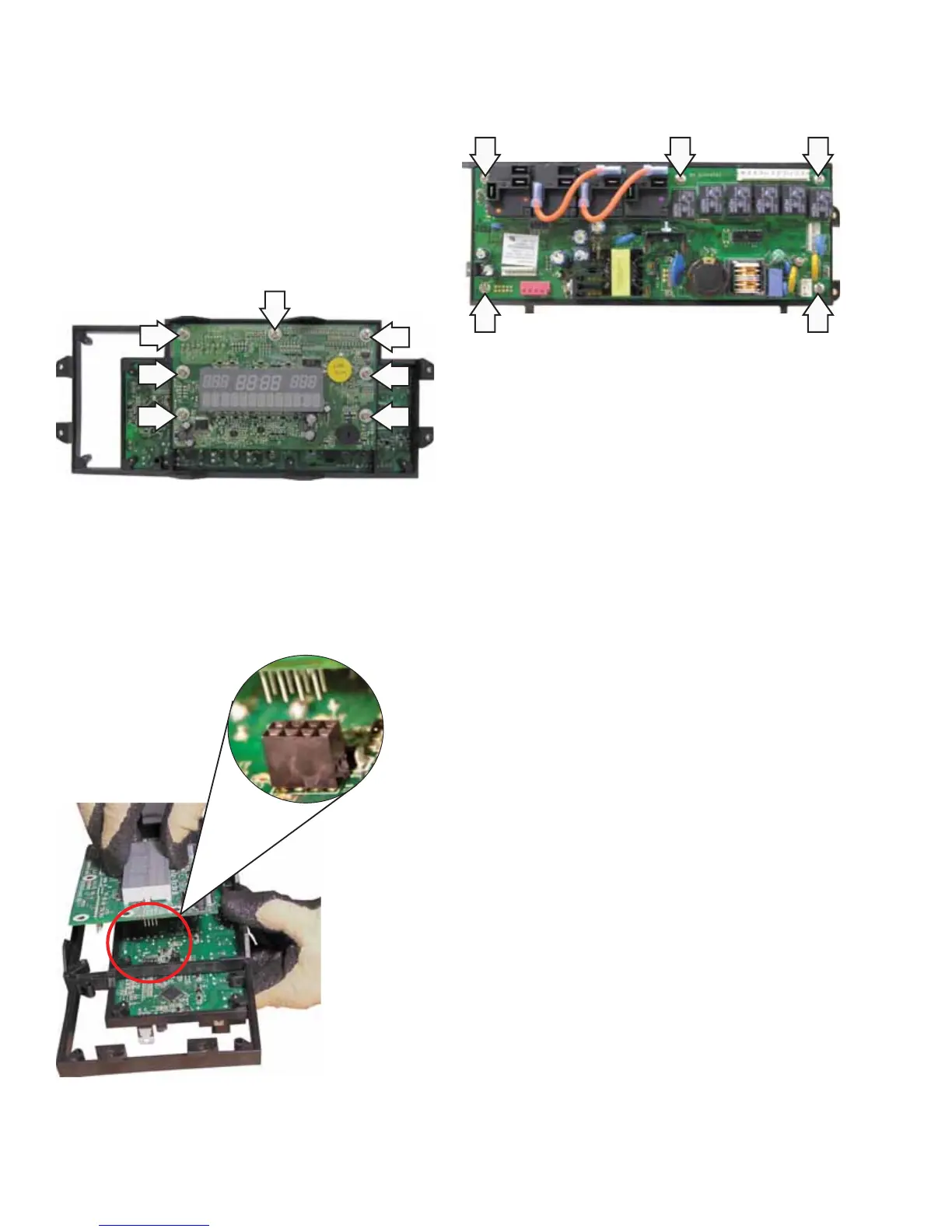
Caution: The screws that attach the display board
are slightly longer than the screws that attach
the control board. To avoid damage to the ERC
assembly, install screws in their original locations.
Remove the 7 Phillips-head screws that attach 5.
the display board to the ERC assembly frame.
Note: The display board is connected to the control
board utilizing an 8-pin plug located between the
boards.
Pull the display board straight out from the 6.
control board.
Turn the frame over and remove the 5 Phillips-7.
head screws that attach the control board to the
ERC frame.
Note: If replacing the ERC, transfer the model
selector harness to the replacement ERC in the
same location as on the original.
8-Pin Plug



 To Next Page