– 20 –
Installation
Electrical Requirements
Caution: For personal safety, do not use an
extension cord with this appliance.
This appliance must be supplied with the proper
voltage and frequency, and connected to an
individual properly grounded branch circuit,
protected by a circuit breaker or fuse having
amperage as specifi ed on the rating plate. The
rating plate is located on the left-hand side of the
lower oven front frame.
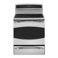
Location of
model rating
plate
Anti-Tip Bracket
WARNING: The range must be secured by the anti-
tip bracket supplied. Unless properly installed, the
range could be tipped by stepping or sitting on the
doors. Injury may result from spilled hot liquids or
from the range itself.
An anti-tip bracket is supplied with instructions for
installation in a variety of locations. The instructions
include all necessary information to complete the
installation. Read the safety instructions and the
instructions that fi t your situation before beginning
installation.
You must use a 3-wire, single-phase A.C. 08Y/120
Volt or 240/120 Volt, 60 hertz electrical system. If
the electrical service provided does not meet the
above specifi cations, have a licensed electrician
install an approved outlet.
WARNING: ALL NEW CONSTRUCTIONS, MOBILE
HOMES AND INSTALLATIONS WHERE LOCAL CODES
DO NOT ALLOW GROUNDING THROUGH NEUTRAL,
REQUIRE A 4-CONDUCTOR UL-LISTED RANGE CORD.
Use only a 3-conductor or a 4-conductor UL-listed
range cord. These cords may be provided with ring
terminals on wire and a strain relief device.
A range cord rated at 40 amps with 125/250
minimum volt range is required. A 50-amp range
cord is not recommended but, if used, it should
be marked for use with nominal 1
3
/
8
-in. diameter
connection openings. Care should be taken to
center the cable and strain relief within the knockout
hole to keep the edge from damaging the cable.
Because range terminals are not accessible after
range is in position, fl exible service conduit or cord
must be used.
Typical installation of anti-tip bracket attachment to wall
Bracket
Screw must
enter wood
or metal
Wall plate
Element Size and Wattage
BOOST MODE AND POWER SHARING
The induction coils on the left side are paired
for power sharing and both cannot be used
simultaneously on “H.” The last coil set to “H” will
remain on “H” and the other coil will reduce to
power level “7½.” The induction coils on the right
side are likewise paired for power sharing. The last
coil set to “H” will remain on “H” and the other coil
will reduce accordingly (RF coil will reduce to “7” and
the RR coil will shut off).
7" - 2500 Watts
7" - 2500 Watts
11" - 3700 Watts
6" - 1800 Watts
Warmer
100 Watts
 Loading...