TheoryofOperation
J13ACPowerto+24VPowerSupply(cont'd.)
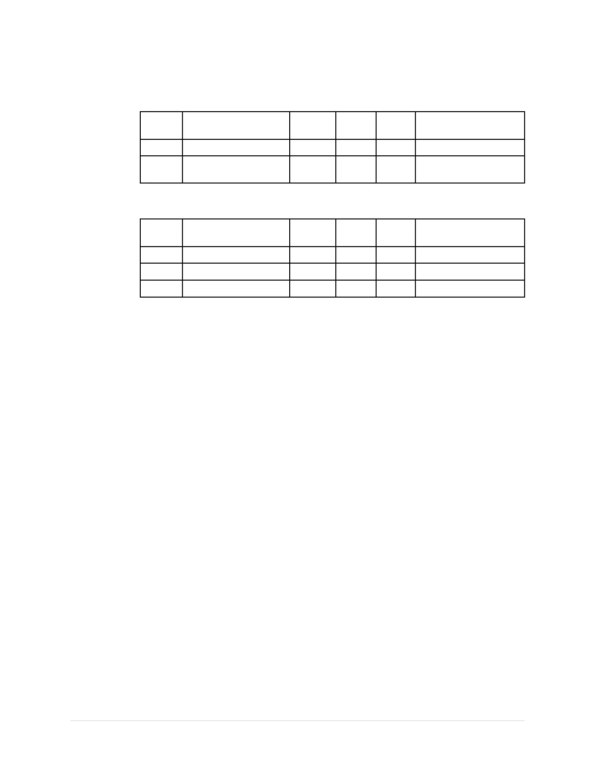
PIN#NAMETYPE
IN/
OUT
FREQCOMMENT
J13–3NCNCNC
J13–4
LINEPWR
OUT50-60
Hz
LinePowerOut
J14PowerCabletoProcessorBoard
PIN#NAMETYPE
IN/
OUT
FREQCOMMENT
J14–1+5VISO
PWR
OUTDC
ISOPowerSupply
J14–1ISOGNDCOMOUTDC
ISOGroundSupply
J14–1+VUNREG
PWR
OUTDC
ISOPowerSupply
ProcessorBoard(PCB)Theory
GeneralDescription
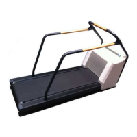
TheprocessorboardandpowerboardfunctiontogethertocontroltheT2100
Treadmill.Theprocessorboardcontainsthefollowing:
•Micro-controllerCPUcircuitry(MC9S12DG128)
•FlashMemory(calibration/historydata)
•Temperaturesensor
•Serialcontrollinks
•I/Ocircuitry
TheI/Ocircuitryreceiveinputsfromastresssystemcontrolleralongwithfeedback
fromtheT2100Treadmillsensorstocontroltheelevationanddriverelayslocatedon
thepowerboard.
PowerDistribution
Theprocessorboardreceivestwosourcesof5-voltpowerfromthepowerboard:an
isolatedsupply,andanon-isolatedsupply.Bypasscapsdistributedacrosstheboard
minimizeEMIandpowersupplynoise.
ClockGenerator
A16.00MHzoscillatorinacolpittscongurationisusedtoprovidetheprocessor
clock.Thiscongurationcreatesasmallamplitude(1Vp-p)sinusoidmountedona
DCbiasleveltominimizeEMI.
2021403-120F
T2100Treadmill
63


 To Next Page