GE
D
IRECTION GB091046, REVISION 2 VIVID E9 / VIVID E7 BT’13 SERVICE MANUAL
Chapter 8 - Replacement procedures 8 - 231
8-11-1-3 Back End Processor (BEP) removal procedure
Follow these steps to remove the BEP:
1.) Disconnect all I/O cables.
2.) Disconnect the cables at the top of the BEP.
3.) Unlatch the two latches that clamp the printer bracket to the top of the BEP.
DO NOT TOUCH ANY BOARDS WITH INTEGRATED CIRCUITS PRIOR TO TAKING THE
NECESSARY ESD PRECAUTIONS.
1. ALWAYS CONNECT YOURSELF, VIA AN ARM-WRIST STRAP, TO THE ADVISED
ESD CONNECTION POINT LOCATED ON THE REAR OF THE SCANNER (NEAR THE
POWER CONNECTOR).
2. FOLLOW GENERAL GUIDELINES FOR HANDLING OF ELECTROSTATIC SENSITIVE
EQUIPMENT.
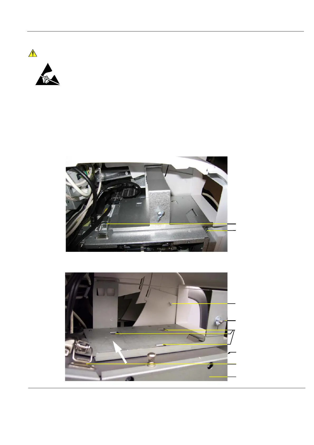
Figure 8-183 Printer Bracket (BEP6)
Figure 8-184 Printer Bracket (first version for BEP5)
LOWER COLUMN COVER
STOP TAB
LATCH (NOT SHOWN)
TABS (3x)
BEP COVER
PRINTER BRACKET
WING NUT
LATCH