GE
D
IRECTION GB091046, REVISION 2 VIVID E9 / VIVID E7 BT’13 SERVICE MANUAL
8 - 232 Section 8-11 - Back End Processor (BEP) parts replacement
8-11-1-3 Back End Processor (BEP) removal procedure (cont’d)
4.) Tilt the Front Cover forward just until the Column Cover Stop Tabs clear.
5.) Lift the Lower Column Cover.
6.) Push the printer bracket toward the FEP approximately 1.3 cm (1/2 inch) to free the 3 tabs from the
BEP. Push in the direction of the white arrow in Figure 8-184.
7.) Remove the BEP Cover.
a.) Loosen the BEP Cover’s fixing screw(s).
- On BEP6 there are two finger screws on the top of the BEP Cover.
b.) Tilt the top of the BEP Cover away from the BEP.
c.) Set the BEP Cover aside.
8.) Remove the Printer Bracket from the BEP.
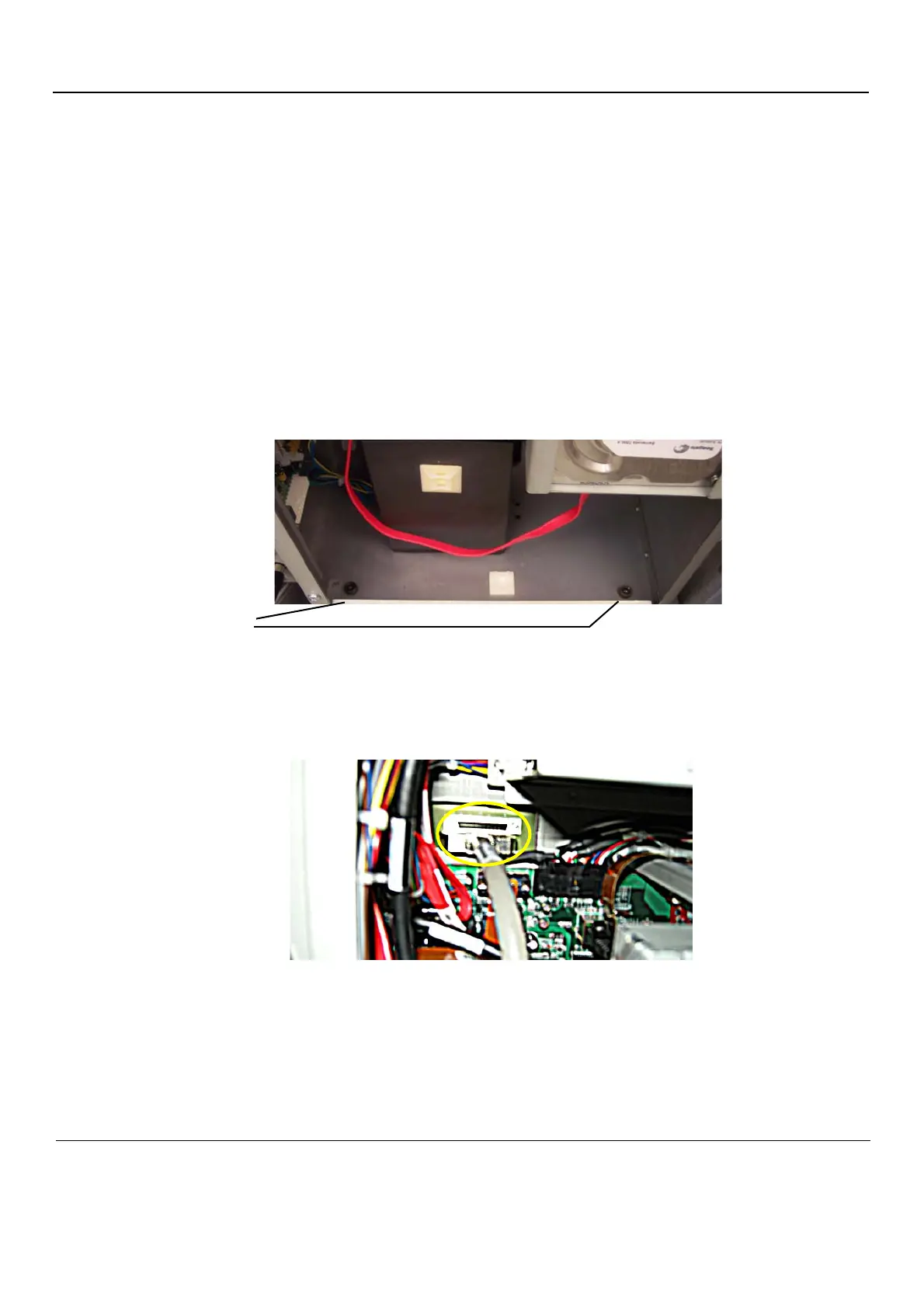
9.) Remove the two hex key screws at the inside base of the BEP.
10.)Reach inside the BEP and disconnect the Boundary Scan Cable from the the FEP Backplane
Connector. It is available through a cut out in the BEP’s Rear Cover.
11.)Slide the entire BEP out of chassis.
Figure 8-185 BEP hex key screws
Figure 8-186 Boundary Scan cable connects BEP to Back Plane (BEP5 is illustrated)