GE
D
IRECTION GB091046, REVISION 2 VIVID E9 / VIVID E7 BT’13 SERVICE MANUAL
10 - 26 Section 10-6 - Electrical Safety Tests
10-6-7-2 Generic procedure on probe leakage current (cont’d)
For each combination, the probe must be active to find the worst case condition.
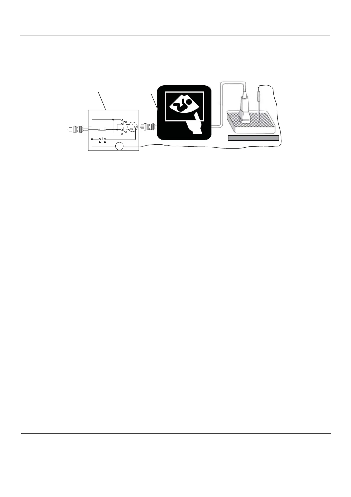
Figure 10-3 Set up for probe leakage current
The ultrasound probe’s imaging area is immersed in the Saline solution along with a grounding probe
from the test meter to complete the current path.
NOTE: Follow manufacturer’s recommendations for handling saline solution. Refer to their Material Safety Data
Sheet (MSDS) for more information.
NOTE: Each probe will have some amount of leakage current, dependent on its design. Small variations in
probe leakage currents are normal from probe to probe. Other variations will result from differences in
line voltage and test lead placement.
1. Ultrasound System
2. Tester
3. Neutral Switch
4. Ground Switch
5. Polarity Reversing Switch
6. Meter
7. Isolator
8. Ultrasound Probe
9. Saline Probe