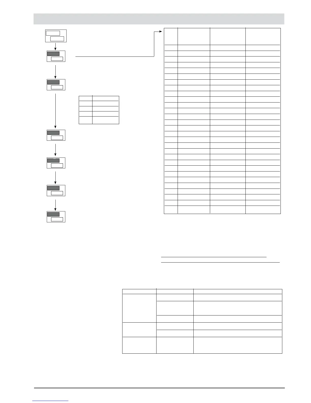
INP Inputs Settings Third menu to set up -Easy-
PV
SV
n
I
P.
---
0
tYP
PV
SV
Type of probe, signal, custom line-
arization enabling and main scale input
TYP Probe type Without dec. With dec.
point point
DP.S = 0 DP.S = 1
Sensore: TC
0 TC J °C 0/1000 0.0/999.9
1 TC J °F 32/1832 32.0/999.9
2 TC K °C 0/1300 0.0/999.9
3 TC K °F 32/2372 32.0/999.9
4 TC R °C 0/1750 0.0/999.9
5 TC R °F 32/3182 32.0/999.9
6 TC S °C 0/1750 0.0/999.9
7 TC S °F 32/3182 32.0/999.9
8 TC T °C -200/400 -199.9/400.0
9 TC T °F -328/752 -199.9/752.0
30 PT100 °C -200/850 -199.9/850.0
31 PT100 °F -328/1562 -199.9/999.9
32 JPT100 °C -200/600 -199.9/600.0
33 JPT100 °F -328/1112 -199.9/999.9
34 PTC °C -55/120 -55.0/120.0
35 PTC °F -67/248 -67.0/248.0
36 NTC °C -10/70 -10.0/70.0
37 NTC °F 14/158 14.0/158.0
38 0...60 mV -1999/9999 -199.9/999.9
40 12...60 mV -1999/9999 -199.9/999.9
42 0...20 mA -1999/9999 -199.9/999.9
44 4...20 mA -1999/9999 -199.9/999.9
46 0...10 V -1999/9999 -199.9/999.9
48 2...10 V -1999/9999 -199.9/999.9
50 0...5 V -1999/9999 -199.9/999.9
52 1...5 V -1999/9999 -199.9/999.9
54 0...1 V -1999/9999 -199.9/999.9
56 200 mV...1 V -1999/9999 -199.9/999.9
CUSTOM linearization:
L0 appears when the variable takes on values lower than the
LO.S parameter or the minimum calibration value.
KI appears when the variable takes on values higher than the
K
’
.S parameter or the maximum calibration value.
Maximum Non Linearity error for Thermocouples (TC),
Temperature resitances (Pt100) and Thermistors (PTC, NTC).
The error is calculated as differing from the theroetical value
with reference in % of the full scale value, expressed in degre-
es Celsius (°C)
Decimal Point Pos.
for Input Scale
Probe type Probe Error
Thermocouples TC type J, K < 0,2 % f.s.
TC type S, R with scale 0..1750 °C: < 0.2 % f.s.
(t > 300 °C); for other scales: < 0.5 % f.s.
TC type T < 0.2 % f.s. (t > -150 °C)
Thermistors NTC < 0.5 % f.s.
JPT100 / PTC < 0.2 % f.s.
Temperature Pt100 with scale -200..850 °C: accur. better
than resistances 0.2 % f.s.
DP.S Format
0 xxxx
1 xxx.x
2 xx.xx (*)
3 x.xxx (*)
Main Input Scale MAX Limit Valore
Min..Max value assigned to input
selected with the TYP parameter
Lower limit for SP and absolute
alarms LO.S ... KI.S
Upper limit for SP and absolute alarms
LO.S ... KI.S
Main Input Scale MIN Limit
Min..Max value assigned to input
selected with the TYP parameter
(*) not available for TC, RTD, PTC, NTC probes.
0
dP.S
PV
SV
0
Lo.S
PV
SV
1000
Ki .S
PV
SV
0
LoL
PV
SV
1000
Ki .L
PV
SV
16
81801G_MHW_1200-1300_07-2011_ENG