Chapter 2 - Installation 33
© 2018 Geist
GM1196 R-Series v5 Instruction Manual
Chapter 3 - Setup
Hardware Interface
The R-Series PDUs have advanced features to support data center needs for full remote
monitoring, logging and alarms, with options for outlet level monitoring and switching
control. The PDUs support multiple I/O options.
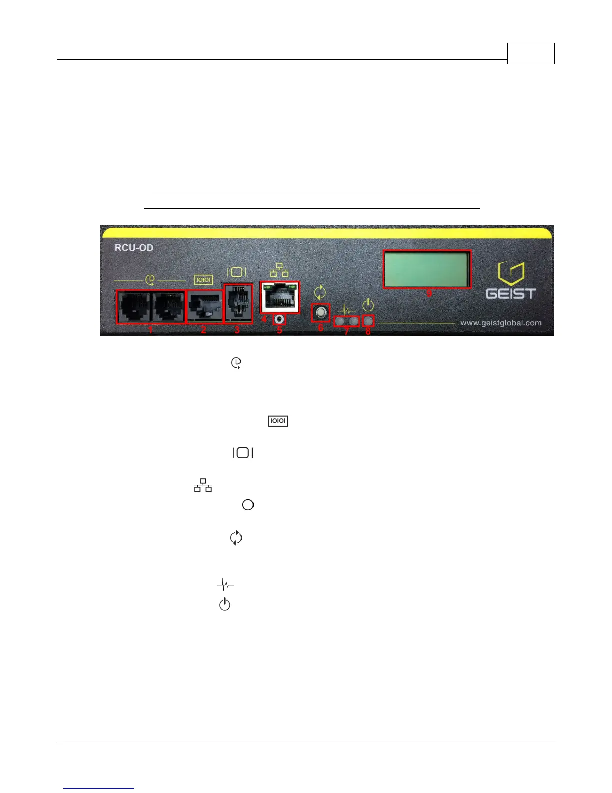
Figure 3-1 RCU-OD Interface
1. Remote Sensor Port ( ): Two RJ12 ports for connecting Geist plug-and-play remote
sensors (sold separately). Splitters may be used to increase the amount of sensors.
Each sensor has a unique serial number and is automatically discovered. R-Series
PDUs support up to sixteen sensors.
2. Serial Communication Port ( ): This RS-232 via RJ-45 port enables the R-Series
PDUs to provide serial access to the command line interface.
3. Remote Display Port ( ): An optional remote display (RSD2X8) can be connected
to the R-Series PDU.
4. Ethernet Port ( ): RJ45 port for connecting the PDU to a TCP/IP network.
5. Network-Reset Button ( ): Holding the network-reset button for 5 seconds during
normal operation will restore the default IP address and reset the user accounts.
6. Hard-Reboot Button ( ): Pressing the hard-reboot button reboots the monitoring
device. This acts as a power-cycle for the device, and does not change or remove any
user information. Note that this will NOT affect power to the outlets.
7. Activity/Idle LEDs ( )
8. Power Status LED ( )
9. Local LCD Display: The local display scrolls through the values of the measurements
selected on the LCD Display page.
For R-Series Switched PDUs, there is an LED next to each outlet providing feedback for
the current state.
· Green: Outlet is on.
· Red: Outlet is off.