Cinterion
®
Java Terminals Hardware Interface Description
8.3 Configuration via ASC0 Interface
69
EHSxT_BGS5T_HID_v02 2014-05-23
Confidential / Preliminary
Page 63 of 70
8.3.1.10 Set GPIO Direction
This command configures the input/output direction of level-shifters to the module‘s externally
available GPIO pins. The argument is a 10-bit number, representing the 10 adjustable direc-
tions of the GPIO level-shifters. A set bit (value 1) sets the respective level-shifter to the output
direction. A cleared bit changes the respective level-shifter to input direction. The following ta-
ble describes the connection between the 10-bit argument number, the modules GPIO pins,
and the Java Terminals Weidmueller connectors 8-pin and 12-pin:
Changing the directions of the level-shifters must be executed with great care. They may only
be set in accordance with the modules GPIO‘s input/output configuration. Special care must be
taken that no outputs are cross-connected during the switching phase.
Configuring a Java terminal output, the level shifter output must be set first, followed by the
module output configuration.
Configuring a Java terminal input, the module input must be set first, followed by the level shift-
er input.
Please note that the GPIO direction can also be configured via I
2
C interface. It is recommended
to use the I
2
C interface to configure the GPIO direction.
Note: Not every GPIO is supported by every Java Terminal variant - see Section 3.7.
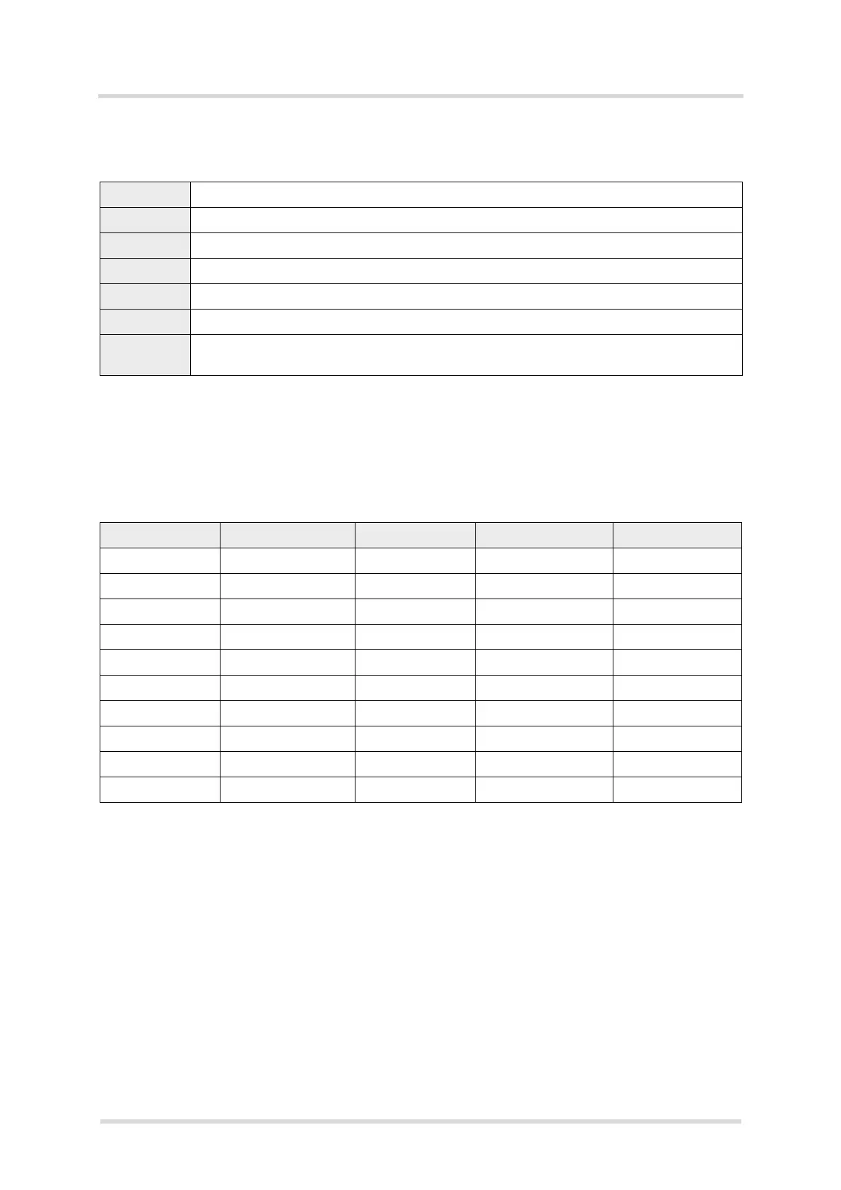
Command GPIO_DIR
Parameter <pin-config>
Type Number
Range 0-1023
Default 993 (0x3E1, 1111100001b)
Non-volatile Yes
Example WD= GPIO_DIR,682,16 // Sets the GPIOs alternating to output and input
(binary value: 1010101010b)
10-Bit number GPIO 8-pin connector 12-pin connector Default
0 GPIO6 1 - Output
1GPIO72- Input
2GPIO83- Input
3 GPIO11 4 - Input
4 GPIO12 5 - Input
5 GPIO13 6 - Output
6 GPIO14 7 - Output
7 GPIO15 8 - Output
8 GPIO21 - 12 Output
9 GPIO20 - 11 Output
 Loading...