PART 6
DISASSEMBLY
Page 158
Section 6.1
Major Disassembly
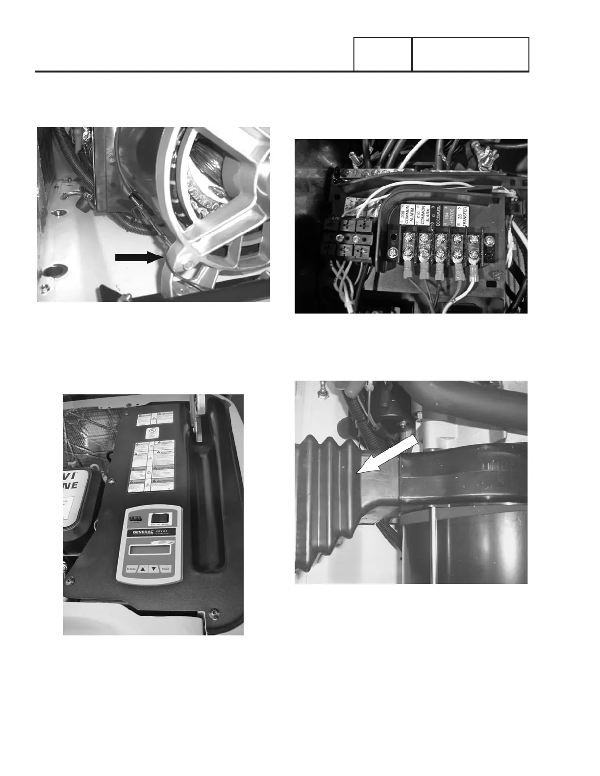
12. Remove Brush Wires: Using a side cutters remove the tie
wraps securing the brush wires to the outside of stator.
See Figure 196.
Figure 196.
13. Remove Controls Cover: Using a Torx T-27 socket or
5/32” Hex Allen socket remove two bolts and ground
washer from the controls cover. Remove the controls
cover. See Figure 197.
Figure 197.
14. Remove Stator Wires: Remove all connectors from
the controller, remove all wires the common neutral and
ground wires from landing lugs, and remove wires from
main beakers. See Figure 198.
Figure 198.
15. Alternator Air Intake Bellows Removal: Remove
alternator intake bellows. See Figure 199.
Figure 199.
16. Rear Bearing Carrier Removal: Using a 13mm socket,
remove the two nuts from the alternator mounting bracket
rubber mounts. Lift the back end of the alternator up and
place a 2”x 4” piece of wood under the engine. See Figure
201. Using a 13mm socket, remove the four stator hold
down bolts. See Figure 201. Using a small rubber mallet
remove the rear bearing carrier. See Figure 201. Remove
stator. See Figure 202.
 Loading...


