Activation and Startup
12 Owner’s Manual for Stationary Diesel Generators
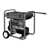
Figure 3-4. Prime Fuel System (2.5L Engines)
2. When all bubbles are purged and replaced by a solid
stream of fuel, lower pump handle (or release
priming bulb) and tighten the air bleed screw.
Install Battery
2.5L Models
NOTE: Remove ten screws to release louvered air
intake panel on left side of enclosure.
1. Loosen two screws with nylon washers to release
hold-down clamp from battery tray, or loosen strap
and move away from tray.
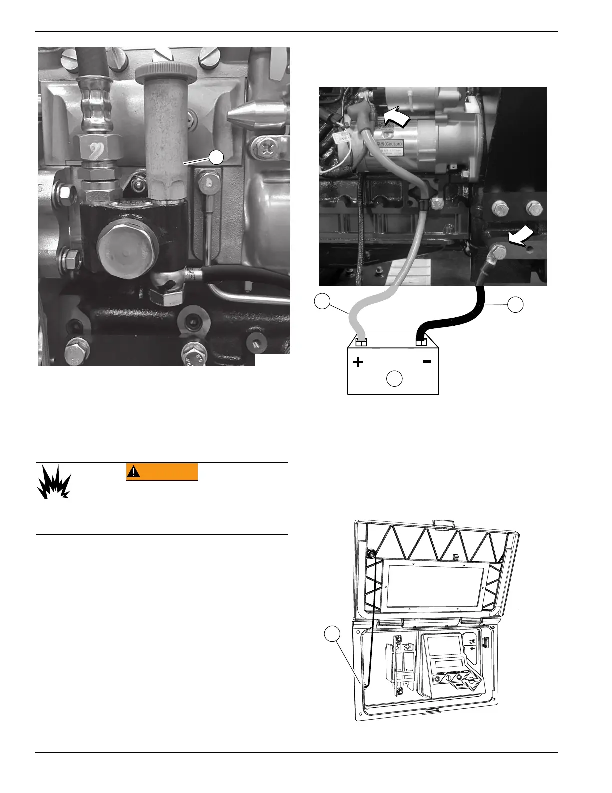
2. See Figure 3-5. Place battery (C) on tray.
3. Install two screws with nylon washers to secure
hold-down clamp to battery tray, or tighten strap
over top of battery.
4. Connect positive battery cable (red) (A) to positive
(+) battery terminal.
5. Connect negative battery cable (black) (B) to
negative (-) battery terminal.
6. Thread ten screws into louvered air intake panel.
Alternately tighten screws to 90 in-lb (10 Nm) using
a crosswise pattern.
Figure 3-5. Battery Cable Connections
Open Viewing Window
1. Rotate viewing window upward to access control
panel.
2. See Figure 3-6. To hold viewing window in the
open position, remove rod from clip at back of
window and insert into hole in frame (A).
Figure 3-6. Viewing Window
(000133)
WARNING
Explosion. Batteries emit explosive gases.
Always connect positive battery cable first to
avoid spark. Failure to do so could result in
death or serious injury.