Maintenance
Owner’s Manual for Stationary Diesel Generators 35
NOTE: Use a solution of soap and warm water to clean
pulleys, if necessary. Avoid use of solvents, but if used,
always follow by a soap and water wash.
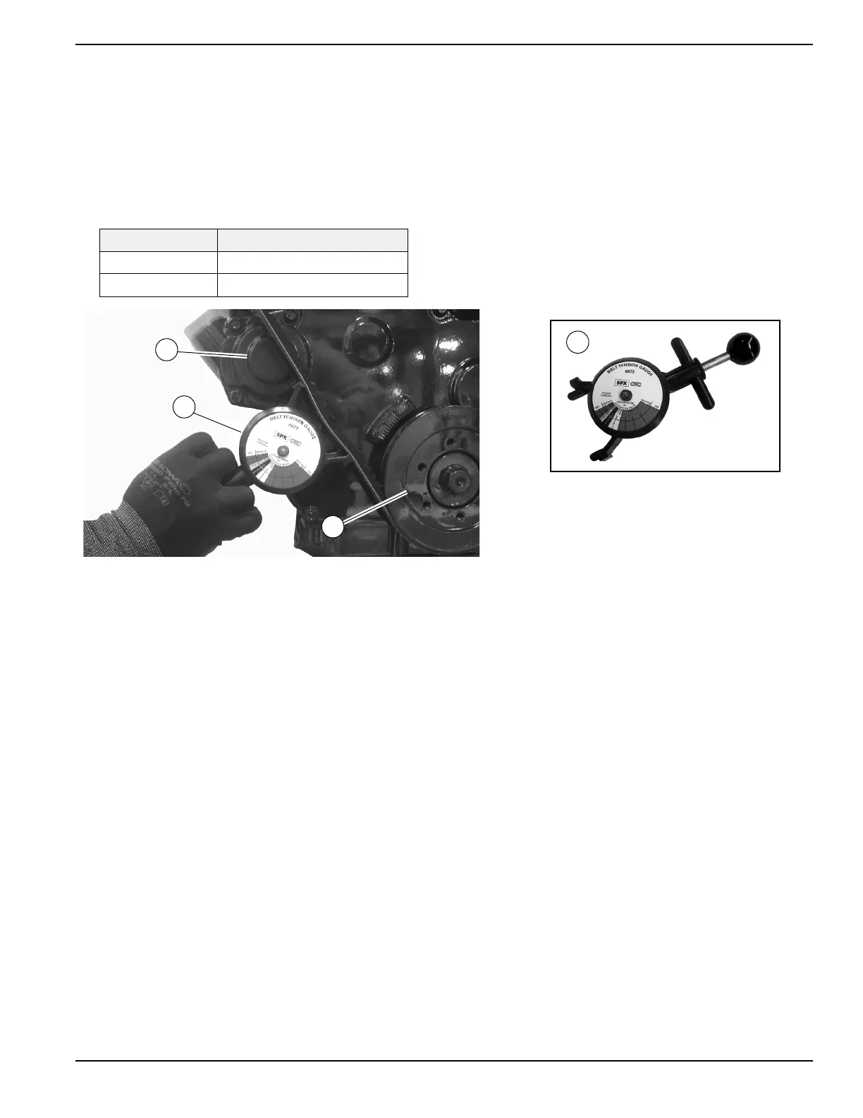
4. Using a suitable belt deflection gauge (A), apply 22
Ibs (10 kg) force midway between the crankshaft
(B) and alternator pulleys (C). See Figure 5-13.
5. Take note of gauge reading. If belt deflection is not
within specification, see Adjust V-Belt Tension
.
6. Install four screws with nylon washers to fasten fan
guard to radiator shroud.
7. Install clamps and rubber couplings onto each end
of turbocharger exhaust outlet pipe. Install pipe to
turbocharger outlet and radiator shroud. Tighten
clamps.
Figure 5-13. Check V-Belt Deflection
Adjust V-Belt Tension
1. Loosen tension adjuster screw (top). Loosen hex
nut on pivot screw (bottom). Rotate alternator
outward to reduce belt deflection, rotate inward to
increase belt deflection.
2. Tighten tension adjuster screw (top) to 17-22 ft-lbs
(23-30 Nm). Tighten hex nut on pivot screw
(bottom) to 33-43 ft-lbs (45-58 Nm).
3. Recheck belt deflection and repeat steps as
necessary.
Belt Condition Deflection
New 0.31–0.47 in (8–12 mm)
Used 0.39–0.59 in (10–15 mm)