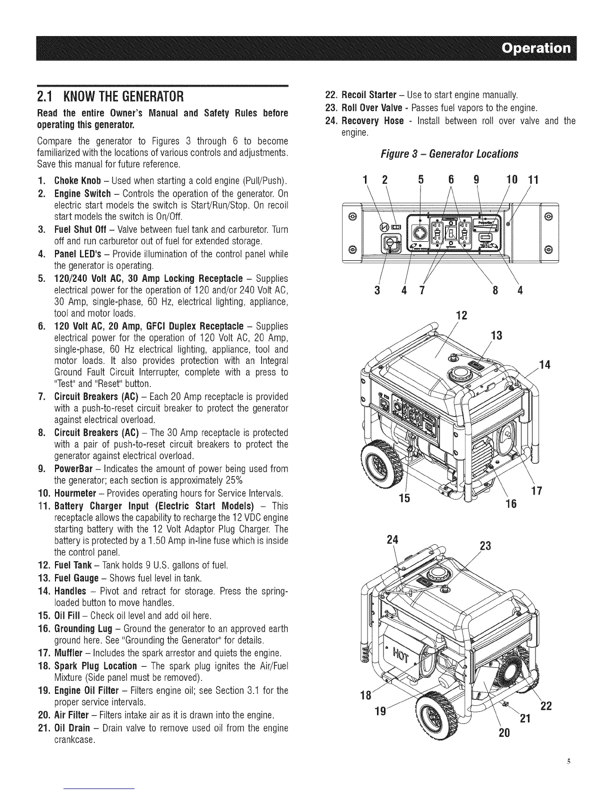
2.1 KNOWTHEGENERATOR
Read the entire Owner's Manual and Safety Rules before
operatingthisgenerater.
Compare the generator to Figures 3 through 6 to become
familiarizedwith thelocationsof variouscontrols andadjustments.
Savethis manualfor future reference.
1. ChokeKnob- Usedwhen starting a coldengine (Putt/Push).
2. EngineSwitch - Controlsthe operation of the generator.On
electric start models the switch is Start/Run/Stop.On recoil
start modelsthe switch is On/Off.
3. FuelShut Off - Valvebetweenfuel tank and carburetor.Turn
off and run carburetoroutof fuelfor extendedstorage.
4. Panel LED's- Provideilluminationof the control panelwhile
thegeneratoris operating.
5. 120/240 Volt AC, 30 Amp LockingReceptacle- Supplies
electricalpowerfor the operationof 120 and/or 240 VoltAC,
30 Amp, single-phase, 60 Hz, electrical lighting, appliance,
tool andmotor loads.
5. 120 Volt AC, 20 Amp, GFCiDuplexReceptacle- Supplies
electrical power for the operation of 120 Volt AC, 20 Amp,
single-phase, 60 Hz electrical lighting, appliance, tool and
motor loads. It also provides protection with an Integral
Ground Fault Circuit Interrupter, complete with a press to
"Test"and "Reset"button.
7. Circuit Breakers (AC) - Each20 Amp receptacleis provided
with a push-to-reset circuit breakerto protect the generator
againstelectricaloverload.
8. Circuit Breakers (AC) - The 30 Amp receptacleis protected
with a pair of push-to-reset circuit breakersto protect the
generatoragainstelectricaloverload.
9. PowerBar- Indicatesthe amountof power being used from
thegenerator;each sectionisapproximately25%
10. Hourmeter - Providesoperatinghoursfor Service Intervals.
11. Battery Charger Input (Electric Start Models) - This
receptacleallowsthe capabilityto rechargethe 12 VDCengine
starting battery with the 12 Volt Adaptor Plug Charger.The
batteryisprotectedby a 1.50 Ampin-linefuse which is inside
thecontrol panel.
12. FuelTank- Tankholds 9 U.S.gallons of fuel.
13. FuelGauge- Showsfuel levelin tank.
14. Handles - Pivot and retract for storage. Press the spring-
loadedbuttonto move handles.
15. Oil Fill - Checkoil levelandadd oil here.
16. GroundingLug - Groundthe generatorto an approvedearth
groundhere.See"GroundingtheGenerator"for details.
17. Muffler- Includesthe sparkarrestor andquietsthe engine.
18. Spark Plug Location - The spark plug ignites the Air/Fuel
Mixture(Sidepanelmust be removed).
lg. Engine Oil Filter- Filtersengineoil; seeSection 3.1 for the
properservice intervals.
20. Air Filter- Filters intakeair as it is drawn intothe engine.
21. Oil Drain- Drain valveto remove used oil from the engine
crankcase.
22. RecoilStarter - Useto start enginemanually.
23. Roll Over Valve- Passesfuel vaporsto the engine.
24. Recovery Hose - Install between roll over valve and the
engine.
Figure 3 - Generator Locations
1 2 5 B 9 10 11
@ [_ , ,,,. ,, , ,:, @
4 7
12
13
17
15 18
24
23
18
1
22
2O
 Loading...