- 43 -
3.3.4 Installation
Spread grease on the oil seal at the brake disc.
Spread grease on the gearing mesh and the active parts of
speed indicator.
Install the brake disc after meshing between gears of speed
indicator and the bearing claws.
Note
•If the bearing claws do not mesh, the claws may be
distorted when screwing up the nuts.
•Rotate the wheel after mounting the wheel spindle to
confirm whether the driven shaft of speed indicator
rotates.
Mount the wheel spindle nuts and tighten them.
*Remark:please refer to Page 41 for the disassembly
and assembly diagram of QJ50-23 and QJ50-23A.
Torque force
Front wheel spindle 55-62 N·m
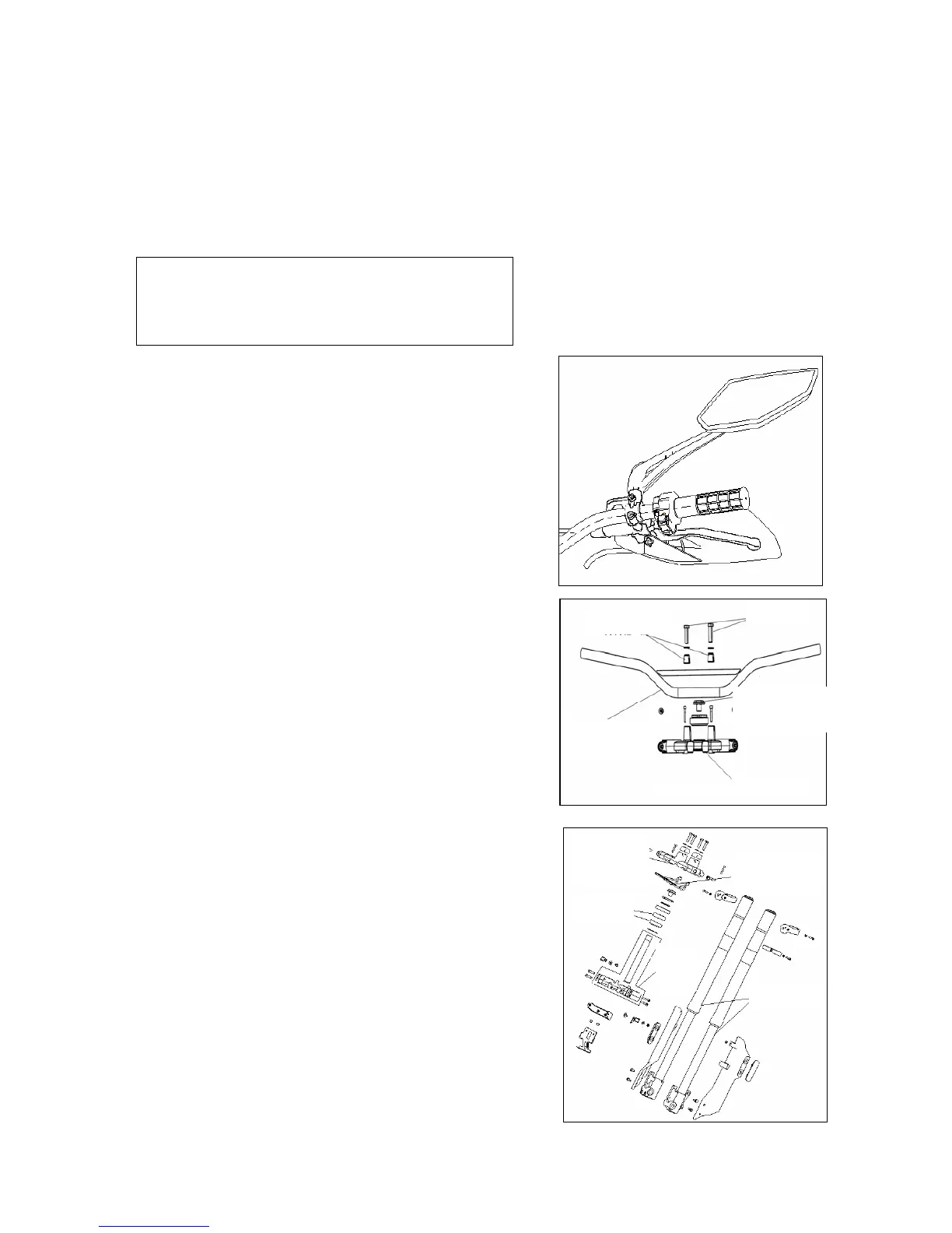
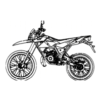
3.4 Steering handle
3.4.1 Disassembly
Disassemble the steering handle sleeve.
Disassemble the fixing bolts on brake rod and unload the
bracket.
Disassemble the bracket of rear brake rod.
Remove the throttle handle and bolts.
Remove the throttle handle and the
Throttle cable.
Remove the fixing bolts of handle and unload the handle.
3.4.2 Installation
Installation is conducted in the reverse order of
disassembly.
Fixing bolt
Torque value :5-9 N·m
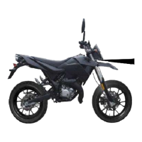
3.5 Front fork
3.5.1 Disassembly
Disassemble the front mudguard.
Disassemble the front wheel.
Disassemble the brake wire and speed indicator wire.
Disassemble the front shock absorber.
Disassemble the fixing nut.
Disassemble the steering handle.
fixing bol