- 58 -
5.5 Voltage and current regulator
5.5.1 Inspect the main wire circuit
Unload the body guard, pad and oil tank.
Disassemble the 4P plug of the voltage and current
regulator, inspect the conduction between main wire
terminals with the following methods.
Item(wire color) Judging method
between the battery
(red)and body ground
there being battery
voltage
between the ground
wire(black)and body
ground
there being wire
between the
illuminating line
( pink )and body
ground(inspect the
resistor plug and plug of
the side auto-starter
when the lighting
switch is pushed to OFF
position)
there being resistance
in alternator coil
between the charge coil
(white)and body
ground
there being resistance
in alternator coil
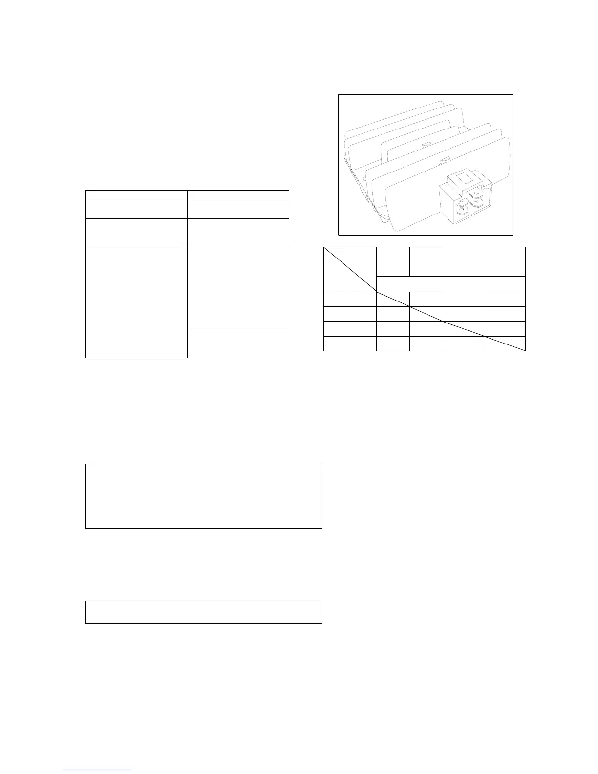
5.5.2Inspectthe voltage and current
regulator
If the main wire terminal proves fine after inspection,
inspect whether the current regulator plug is in poor contact
and measure the resistance value between the terminals of
the voltage and current regulator.
*Note
•The metal area of the avometer prod mustn't be touched
by fingers during inspection.
•Inspect with an avometer. Different avometers will give
different resistance values, and the inspection result is
incorrect.
If the resistance value between terminals is abnormal, the
voltage regulator should be replaced.
5.6 Charge coil of the alternator
*Note
Inspection of the charge coil of alternator may be
conducted on the engine.
Inspection
Disassemble the 4P joint of alternator.
Measure the resistance value between the white coil of
alternator and the motorcycle frame with an avometer.
white
(A)
red
(L)
pink
(B)
black
(E)
avometer
Positive pole
Negative pole
Unit:KΩ
white(A) 13 6.5 8
red(L) 3 1 0.7
pink(B) 2 4 0
black(E) 2 5 1.2