14
For Help, call 1-800-35-GENIE or visit www.geniecompany.com
CH ATTACH POWER HEAD TO
GARAGE
Installation Step 4:
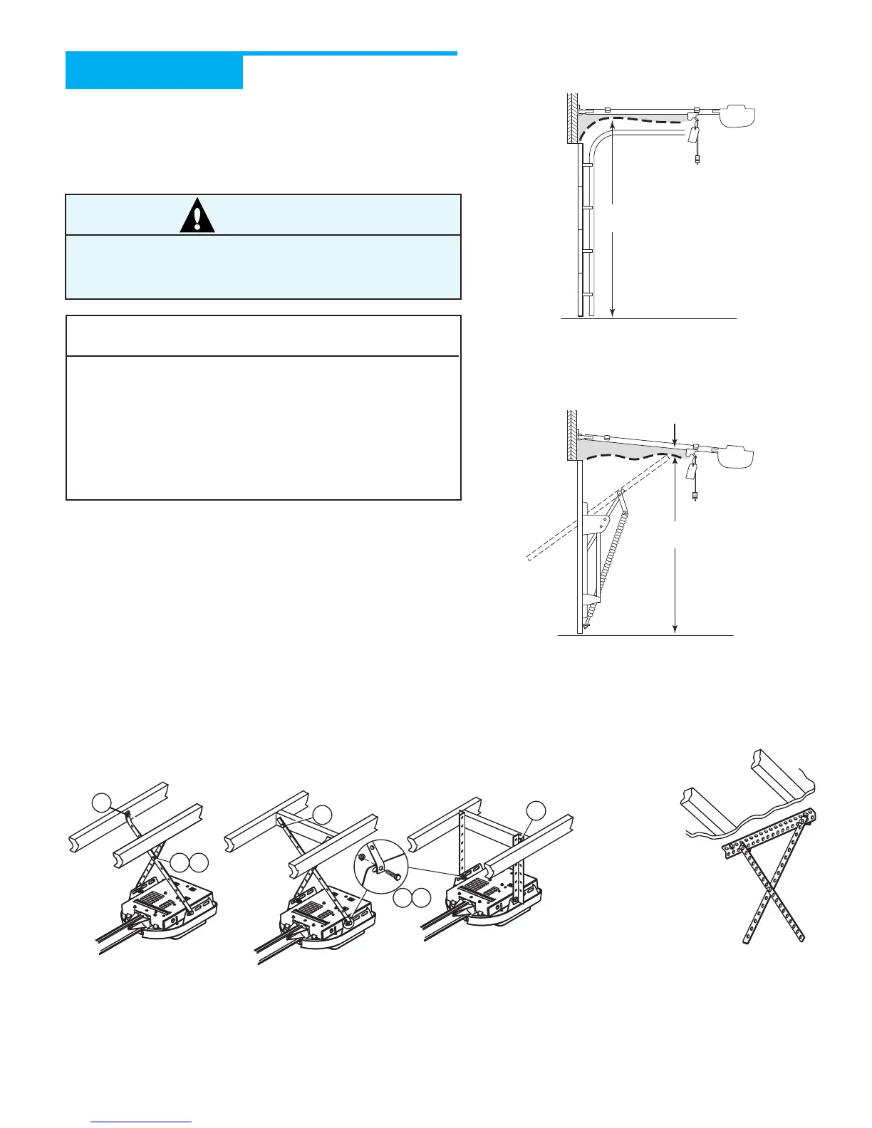
A Raise and support Opener Power Head (along door center
line) higher than highest point of door travel (using step
ladder, etc.) (Figure 21).
B Measure distance from Opener to garage ceiling.
C Install Mounting Straps and/or support brackets (angle iron
not included) to joists or trusses and to mounting slots in
Opener. Use (5/16"-18 x 3/4") Hex Head Bolt, (5/16"-18)
Serrated Flanged Nut, and (1/4" x 2") Lag Screws as needed
(Figure 22).
DSecurely tighten all fasteners now. Do Not over-tighten.
NOTE
• Make sure the rail of your supported Power Head is
slightly higher than the highest point of door travel
by raising the door to check. Adjust as needed.
• Materials needed for mounting Opener Power Head
to garage may vary. Read all instructions completely.
• Garage constructions differ. Extra material may be
needed. See Check Power Head Mounting Area on
page 5.
CAUTION
Mounting Brackets must be fastened to garage framing.
Do Not fasten to drywall, particle board, plaster, or other
such materials.
SECTIONAL DOORS
Rail Should be level or dip down slightly.
Check for clearance.
ONE-PIECE DOORS
Set clearance at 1"-1
1
/2" between Rail and door at
highest point of travel.
Figure 21 Checking Power Head position
Perforated
Angle Iron
OPEN BEAM CEILING EXAMPLES
Figure 22 Mounting methods for open beam and finished ceilings
Mounting Straps
Support board added
for longer spans
(Angle iron not included)
FINISHED CEILINGS
Locate ceiling joists or
trusses using
a stud finder
or similar
device.
Attach angle iron
(not included) to
joists or trusses
through finish material
using Lag Screws.