8
1.2.4 Connecting the PC
The computer running GV-ASManager software can be used to monitor the access
information and alarm messages from GV-AS100. The communication link between the
computer and GV-AS100 can be either through RS-485 or network. For network connection,
an optional GV-ASBox or GV-ASNet is required.
IMPORTANT: To enable connecting to PC, Switch 1 must be turned on. See 1.2.4.C
Switches.
1.2.4.A RS-485 Connection
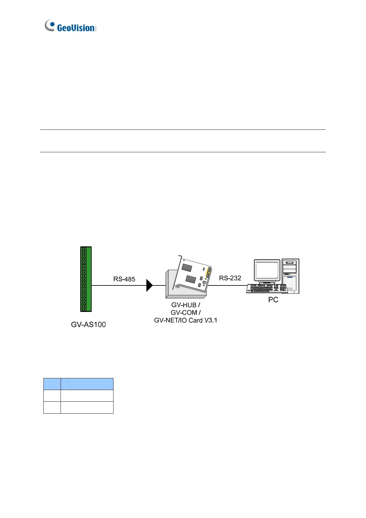
The figure below illustrates the RS-485 connection to the computer. For this connection, a
RS-485 to RS-232 converter between GV-AS100 and the computer is required. You can use
GV accessories, such as GV-Hub, GV-COM and GV-NET/IO Card, as the RS-485/RS-232
converter.
Figure 1-6
The table shows the pin assignments of related RS-485 connectors on GV-AS100.
Pin Function
3 RS-485 A+
4 RS-485 A-

 Loading...


