GV-AS400 Controller
79
3
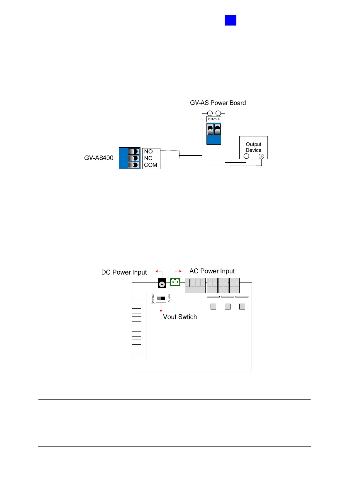
To connect an output device:
Connect the (+) point on the output device to COM on GV-AS400, connect the two (-) points
of the output device and GV-AS Power Board together, and connect the (+) power output on
GV-AS Power Board to the NO or NC on GV-AS400 based on the state of the output device.
Figure 3-35
3.6.3 Connecting the Power
GV-AS Power Board accepts the power input of either 24V AC or 24V DC. After wiring the
power source to the proper connectors on GV-AS Power Board, turn the Vout Switch to the
power current that is connected.
Figure 3-36
Note:
1. If the power input is 24V AC and the Vout Switch is set to DC Output, the voltage of GV-
AS Power Board supplies will be enlarged to 30V DC.
2. Power should only be applied to the unit when all connections are completed and tested.

 Loading...


