Performance Verification
2500A Series Operation Manual, 34172 Revision C, March 2008
4.3.2.3.5 Procedure - Step Attenuator Level Accuracy Test
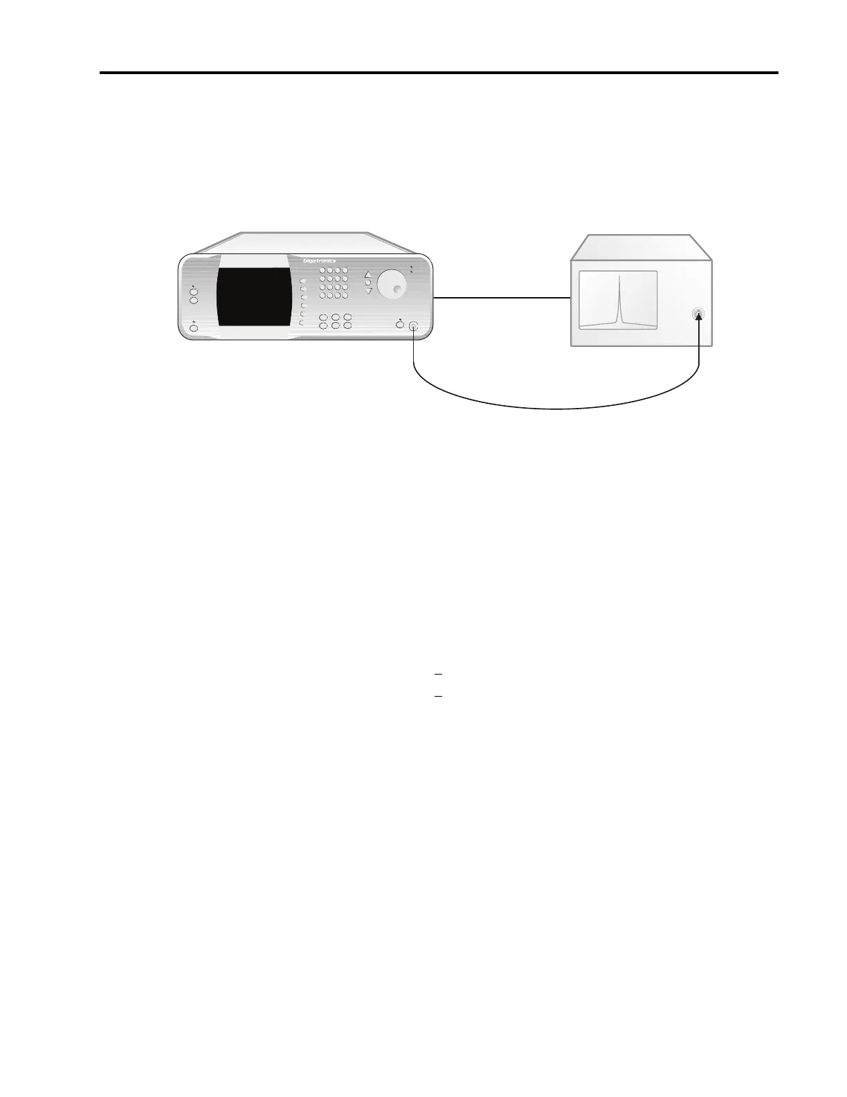
Figure 4-4: Step Attenuator Level Accuracy Test
1. Connect the test equipment and UUT as shown in Figure 4-4, connecting the UUT directly to the RF
input of the Spectrum Analyzer.
2. Set the Spectrum Analyzer to the following settings:
Frequency 12 MHz
Reference Level 0 dBm
Span 5 kHz
Sweeptime 400 msec.
Resolution Bandwidth: <
1 kHz
Video Bandwidth: > 1 MHz
3. Set the UUT output power level to -3 dBm.
4. Set the UUT frequency to 12 MHz and activate the output.
5. Press the Peak Search button on the Spectrum Analyzer.
6. Press the Step Size button on the UUT and set the step size to 10 dB.
7. Reduce the RF output level of the UUT in 10 dB increments by pressing the Down Arrow button
while observing the measurement on the Spectrum Analyzer.
8. Record each level measured of the Spectrum Analyzer into the appropriate column of Datasheet 5
for the frequency being tested.
9. Repeat steps 3 through 8 for the remaining test frequencies in Datasheet 5, recording the measured
levels in the appropriate columns of Datasheet 5.
MICROWAVE SYNTHESIZER (UUT)
RF IN
Spectrum Analyzer
RF OUT
2500A Microwave Synthesizer
IN Timebase OUT