Chapter 4: Specifications & Performance Verification
112 2500A Series Operation Manual, 34172 Revision C, March 2008
4.3.3.3.4 Procedure - Pulse Level Accuracy Test
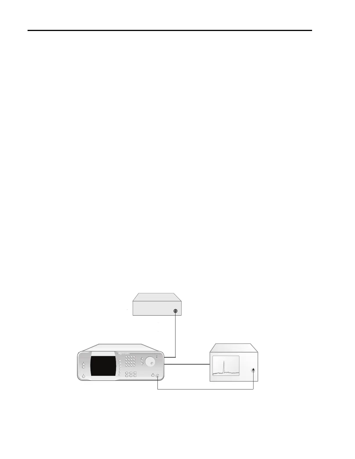
1. Connect the test equipment and UUT as shown in Figure 4-8.
2. Set the Pulse Generator to the following settings:
Pulse Width: 5 msec.
Pulse Interval: 10 msec.
Output: 5 Volts into 50Ω
3. Set the UUT to the following settings:
Power Level: 0 dBm
External PM state: Off
Trigger Polarity: Active high
RF Output state: On
4. Set the power meter’s sensor mode to “CW”.
5. Measure and record the CW level for each of the frequencies listed in Datasheet 10 in the “Level
Accuracy - CW” column of Datasheet 10.
6. Set the External PM state of the UUT to On.
7. Set the power meter’s sensor mode to “Peak,” and adjust the sample delay to 500 nsec.
8. Measure and record the peak level for each of the frequencies listed in Datasheet 10 in the “Level
Accuracy - Pulse” column of Datasheet 10.
9. Compare the CW levels to the peak (Pulse) levels in Datasheet 10, and record the difference in the
“Level Accuracy - Delta” column.
Figure 4-9: Pulse Modulation On/Off Ratio Test
MICROWAVE SYNTHESIZER (UUT)
RF OUT
2500A Microwave Synthesizer
OUTPUT
PULSE IN
(Rear Panel)
Pulse Generator
IN
Timebase
OUT
RF IN
Spectrum Analyzer