Performance Verification
2500A Series Operation Manual, 34172 Revision C, March 2008
4.3.3.3.3 Procedure - Rise and Fall Time Test
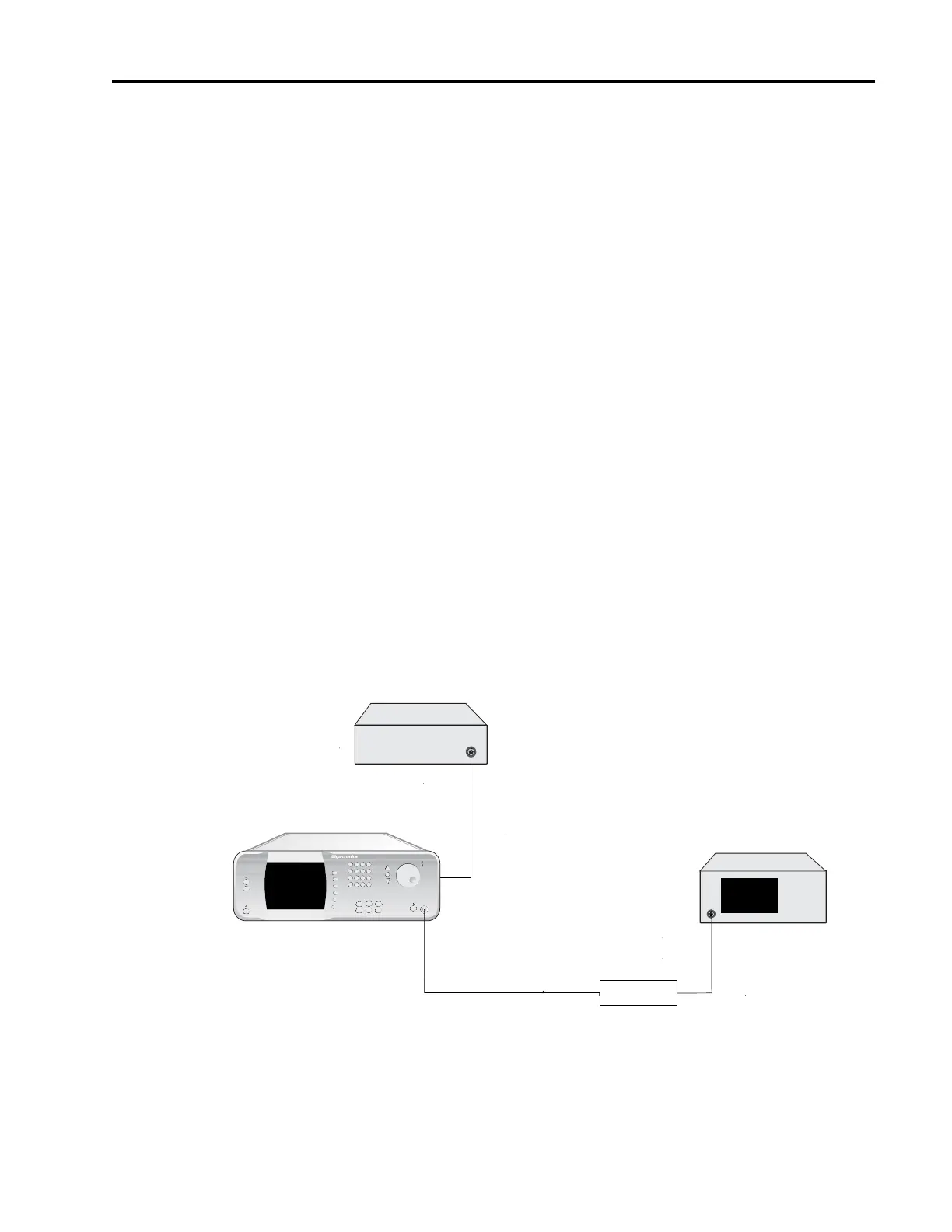
1. Connect the test equipment and UUT as shown in Figure 4-7.
2. Set the Pulse Generator to the following settings:
Pulse Width: 5 msec.
Pulse Interval: 10 msec.
Output: 5 Volts into 50Ω
3. Set the trigger of the Oscilloscope according to the type of Crystal Detector being used (either pos-
itive or negative).
4. Set the UUT to the following settings:
Power Level: 0 dBm
External PM state: ON
Trigger Polarity: Active high
RF Output state: On
5. Set the UUT to the first test frequency shown in Datasheet 10.
6. Measure the rise and fall times on the oscilloscope, and record them in the appropriate columns of
Datasheet
10.
7. Repeat Step 6 for each of the remaining test frequencies shown in Datasheet 10.
Figure 4-8: Pulse Modulation Level Accuracy Test
MICROWAVE
SYNTHESIZER (UUT)
RF OUT
2500A Microwave Synthesizer
OUTPUT
PULSE IN/PM TRIGGER IN
(Rear Panel)
Pulse Generator
Power Meter
SENSOR
IN
SENSOR