Chapter 1: 2500A Introduction
20 2500A Series Operation Manual, 34172 Revision C, March 2008
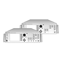
Figure 1-3: 2500A Rear Panel
All rear panel I/O connectors explained in this section are type BNC unless otherwise stated. Some con-
nectors may not be supported because of installed options. For example, Modulation and Modulation
Generator connectors are not active with Option 17A or 17B. Table 1-3 describes the 2500A rear panel
I/O connectors.
Table 1-3: 2500A Rear Panel I/O Connector Descriptions
Connector Label Description
EXT ALC In external leveling, the output of the 2500B is detected by either a positive or negative
crystal detector or power meter with an analog output. The signals from these devices
are connected to the ALC circuitry of the 2500B which is used to compensate for
standing wave effects or cable and component losses at the input of the device under
test.
See Section 4.2.8 for External ALC specifications
RF OUT The RF signal output for the instrument. See Table 1-2 for RF connector types.
It is located on the front panel for all 2500B Series instruments and rear panel for all
2500S Series instruments.
FM OUT
1
The internal modulation generator output;
2 Vp-p into 10k Ω.
PULSE OUT
1
A +4V video representation of the pulsed RF output signal.
AM OUT
1
The internal modulation generator output;
2 Vp-p into 10k Ω.
PM SYNC OUT
1
A synchronization output pulse of >75 ns width, TTL level that can be delayed relative
to the leading edge of the video signal at the PULSE OUT connector.
FM IN
2
A 50 Ω input for an external FM signal. The input signal can be any waveform
compatible within bandwidth considerations. A 1 Vp input produces maximum
deviation.
An externally supplied DC signal can be applied to modulate the frequency of the CW
output using this connector.
See Section 4.2.6 for DC FM specifications
AM IN
2
A 600 Ω input for an external AM signal. The input signal can be any waveform
compatible within bandwidth considerations. A 1 Vp-p input produces 50% AM depth.
PULSE IN/PM TRIG IN
2
A Pulse Modulation Input for external pulse gating, pulse triggering or external Pulse In.
The input parameters are +5 volt, 50 Ω
LOCK/LEVEL +5 volt indicator, active high when the 2500A is phase locked and output leveled. The
Lock and Level indicator is valid for CW mode only.
REF TUNE A 0 to +10 volts, high impedance input for tuning the internal reference for adjusting the
output frequency approximately +
5 ppm. Do not exceed +15 volts or apply a negative
voltage greater than -1 volt.
SYNC OUT In List mode, the unit can be set to generate a pulse at this output when a specified list
point is reached. The output can be delayed from the start of the list point up to a
maximum of 10 msec. The pulse width of the SYNC OUT signal is determined by the
following parameters: pulse width = Step Time - Sync Delay - 10 usec
In Ramp operation, the pulse occurs at the start of each ramp sweep.
In either case, the output pulse is +5 volt.