Hardware Installation - 26 -
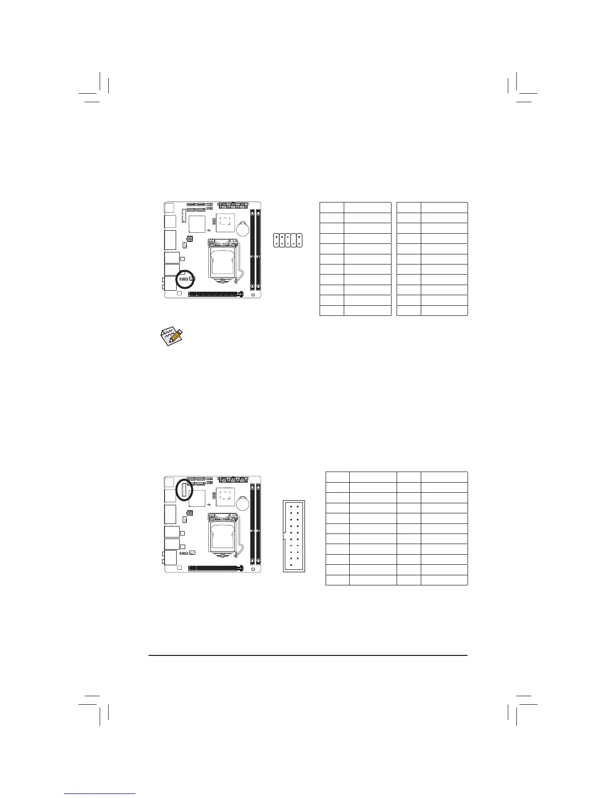
9) F_AUDIO (Front Panel Audio Header)
7KHIURQWSDQHODXGLRKHDGHUVXSSRUWV,QWHO+LJK'H¿QLWLRQDXGLR+'DQG$&DXGLR<RXPD\FRQQHFW
your chassis front panel audio module to this header. Make sure the wire assignments of the module
connector match the pin assignments of the motherboard header. Incorrect connection between the module
connector and the motherboard header will make the device unable to work or even damage it.
The front panel audio header supports HD audio by default. If your chassis provides an AC'97
front panel audio module, refer to the instructions on how to activate AC'97 functionality via the
DXGLRVRIWZDUHLQ&KDSWHU&RQ¿JXULQJ&KDQQHO$XGLR
Audio signals will be present on both of the front and back panel audio connections simultaneously.
If you want to mute the back panel audio (only supported when using an HD front panel audio
PRGXOHUHIHUWR&KDSWHU&RQ¿JXULQJ&KDQQHO$XGLR
Some chassis provide a front panel audio module that has separated connectors on each wire
instead of a single plug. For information about connecting the front panel audio module that has
different wire assignments, please contact the chassis manufacturer.
1
2
9
10
For AC'97 Front Panel Audio:
Pin No. 'H¿QLWLRQ
1MIC
2GND
3 MIC Power
4NC
5 Line Out (R)
6NC
7NC
8No Pin
9 Line Out (L)
10 NC
For HD Front Panel Audio:
Pin No. 'H¿QLWLRQ
1 MIC2_L
2GND
3 MIC2_R
4 -ACZ_DET
5 LINE2_R
6GND
7 FAUDIO_JD
8No Pin
9 LINE2_L
10 GND
Pin No. 'H¿QLWLRQ Pin No. 'H¿QLWLRQ
1 VBUS 11 D2+
2 SSRX1- 12 D2-
3 SSRX1+ 13 GND
4 GND 14 SSTX2+
5 SSTX1- 15 SSTX2-
6 SSTX1+ 16 GND
7 GND 17 SSRX2+
8 D1- 18 SSRX2-
9 D1+ 19 VBUS
10 NC 20 No Pin
10) F_USB30 (USB 3.0/2.0 Header)
7KHKHDGHUFRQIRUPVWR86%VSHFL¿FDWLRQDQGFDQSURYLGHWZR86%SRUWV)RUSXUFKDVLQJWKH
optional 3.5" front panel that provides two USB 3.0/2.0 ports, please contact the local dealer.
20
10 11
1
 Loading...