Start-up and Service Verifying FlexPay EPP Cable Connections
Page 52 MDE-4784D FlexPay™ Encrypting PIN Pad Start-up and Service Manual · December 2011
8 Click Yes.
• If the key map file has been successfully sent to the FlexPay EPP a .txt file for the key map
appears, which displays “0 SYNTAX errors”. See
Figure 3-48 on page 49.
• If the key map file has not been sent to the FlexPay EPP, a .txt file for the key map
appears, which displays the number of SYNTAX errors and the message, “Could not be
sent packet to SM”. See
Figure 3-49 on page 49. After the .txt file is closed, a Warning
window appears. Click OK.
9 Perform steps 3 (on page 51) to 8 to program other FlexPay EPPs, if required.
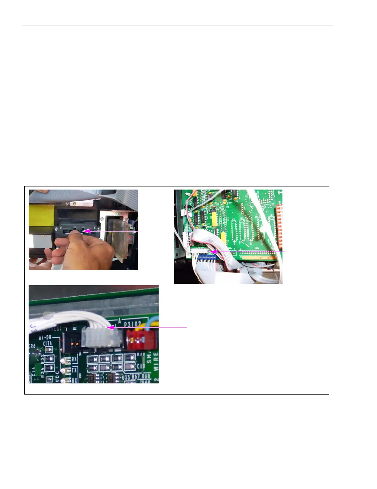
Verifying FlexPay EPP Cable Connections
Figure 3-52: Verifying FlexPay EPP Cable Connections
(i)
(ii)
FlexPay
EPP Cable
connected
to the
FlexPay
EPP
FlexPay EPP
Cable connected
to P282 on the
CRIND Logic
Board
Note: This option
is for The
Advantage
Series and
Encore 300
dispensers
only.
FlexPay EPP Cable connected to
P3101/P3102 on the CRIND Control Node
Note: This option is for Encore 500 Series
and Eclipse dispensers only.
(iii)
Encore 500 Series and Eclipse Dispensers
On Encore 500 and Eclipse dispensers, ensure that one end of the FlexPay EPP cable is
connected to the rear of the FlexPay EPP and the other end to P3102 (SmartPad port) on the
CRIND Control Node for Side A of the unit and P3101 on the CRIND Control Node for
Side B of the unit.
 Loading...