Gill Instruments Ltd
_____________________________________________________________________________________________________________
________________________________________________________________________________________________
WindObserver 65 Page 10 Issue 4
Doc. No. 1390-PS-0039 June 2016
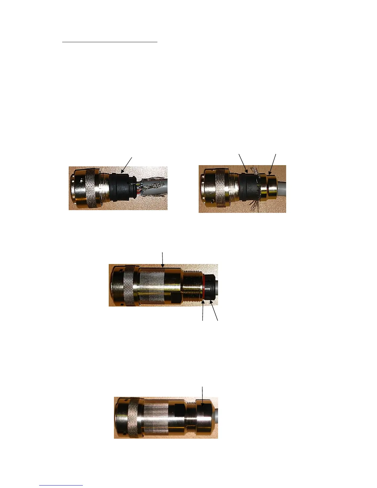
Assemble Connector to the Cable.
Referring to Page 9 push connector contacts through the red connector head seal into the
appropriate location, when in place there should be a click as the contact locks into
position.
Once contacts are in position pass part 6 up the cable and into position as shown below.
Note: if a connector pin needs removing use Cannon Extraction Tool,
Manufacturer’s Part 192922-1450.
Fold and spread screen wires over part 6 and then push up part 5 as shown to clamp screen
wires between Parts 5 and 6.
Now screw in part 4 and torque up to a value of 10Nm.
Pass parts 3 and 2, the cable seal and cable grip from the connector kit, along the cable to
the housing.
Now screw in item 1, the clamp nut, over parts 2 and 3 and onto the housing and torque up
to a value of 10Nm.